background image

Weld Schedules

4 - 2

MedWeld 5000 Technical Reference Manual 

M-032170  

Software Capabilities 

The MedWeld 5000 provides commands for: 

Assigning a stepper to a schedule, 

Defining a linear stepper program, 

Turning selected outputs on or off and 

Providing weld current. 

Other functions enable 

Overriding the setup parameters, 

Controlling the I/O by monitoring inputs and activating outputs, 

Regulating weld current to fall within a prescribed range, and 

repeat the weld if the current is not within that range, 

Statistical process control (SPC) functions, 

Selecting the firing mode (to assure consistent voltage or to assure 

constant secondary current) 

Pausing in a schedule to wait for certain operating conditions to 

become true. 

The software allows users to add or delete functions from this list, or 

change any of the numeric values specified in a function. This allows for 

the creation of a schedule that meets your application requirements. 
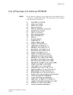
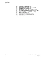
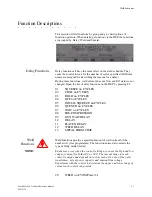
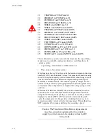
The following sections describe the functions available for use in a weld 

schedule, including the two-digit function code and the action each 

function produces. 
The functions are grouped according to their purpose in a weld 

schedule, and to aid your understanding their overall interaction. 

Summary of Contents for MedWeld 5000

Page 1: ...MedWeld 5000 Integrated Weld Control Technical Reference Manual Software F04100 and F04300 Revision 02 Modified 1 31 06 Part No M 032170 Copyright 2006 WTC...

Page 2: ...MedWeld 5000 Technical Reference Manual Modified 1 31 06 M 032170...

Page 3: ...Getting Started 2 1 Making the Required Connections 2 1 DeviceNet Integration 2 2 Providing MedLAN Connections 2 3 MedLAN and DEP 100S Connections 2 3 MedLAN Wiring Specifications 2 3 Cable Requiremen...

Page 4: ...t 4 15 Default Weld Sequence Machine 4 15 Chapter 5 Advanced Software Features 5 1 C Factor 5 1 Dynamic Current Windows 5 2 AVC Example 5 2 ACC Firing Mode 5 3 SPC Indexing Capabilities 5 4 SPC Functi...

Page 5: ...Modified 1 31 06 Display at the DEP 100S 7 4 Chapter 8 Fault Conditions 8 1 List of Faults 8 2 MFDC Fault Status LEDs 8 3 Chapter 9 Hardware Troubleshooting 9 1 Power Supply 9 1 Processor 9 2 Weld Pro...

Page 6: ...MedWeld 5000 Technical Reference Manual Modified 1 31 06...

Page 7: ...on the serial tag on the inside or front door of the enclosure Also note the sequence of events leading to the problem and the drawing numbers of the schematics you received with the enclosure For yo...

Page 8: ...to observe safety measures may result in death severe bodily injury or serious damage to property WARNING This symbol will be used wherever insufficient or lacking compliance with instructions may re...

Page 9: ...rol Exposure to high voltage WILL CAUSE SEVERE ELECTRICAL BURNS INTERNAL INJURIES and or DEATH Refer all necessary service on this machine ONLY to qualified maintenance personnel Danger NEVER drill in...

Page 10: ...lb use either a two man lift or an assisted lift How to Use this Manual This manual is designed as a reference guide Use it as you would a dictionary See the Table of Contents to locate the instructio...

Page 11: ...or changes as required to the hardware or software described in this manual This manual may be periodically updated to reflect software changes that will affect operation of the equipment described R...

Page 12: ...ead can be significant Reducing losses to ESD and static electricity is an ABSOLUTE NECESSITY Observe the following warnings AT ALL TIMES Danger NEVER use the personnel grounding system described belo...

Page 13: ...stored in the EEPROM distribution media magnetic or CD ROM or in print form without prior written authorization and payment of royalty fees Patents This product contains intellectual property owned or...

Page 14: ...Getting Started xiv Modified 1 31 06 MedWeld 5000 Technical Reference Guide M 032170 This page is intentionally left blank...

Page 15: ...Location Phone Your Name Date Time Program Timer power up message Part Fault code display When a fault or error occurs the Product displays a status code Indicate each code that is displayed Descript...

Page 16: ...Getting Started xvi Modified 1 31 06 MedWeld 5000 Technical Reference Guide M 032170 This page is intentionally left blank...

Page 17: ...Our Training and Documentation staff will review your comments and implement the required corrections in future updates For specific comments fill in the Comments for Feedback form below Fax it at 24...

Page 18: ...Getting Started xviii Modified 1 31 06 MedWeld 5000 Technical Reference Guide M 032170 This page is intentionally left blank...

Page 19: ...monitoring the voltage and increasing the current as required to ensure consistent welds The primary current I changes as the voltage fluctuates for example if the weld energy E drops the timer firing...

Page 20: ...last weld Line cycle or milisecond timing Stepper data and Desired constant current The MFDC is different from traditional single phase welding and high frequency DC welding in the following ways The...

Page 21: ...described below If the LEDs do not turn on during the weld schedule the timer unit may be faulty or the control may be sequencing in No Weld mode PWR This LED lights to indicate that power is being s...

Page 22: ...edWeld 5000 weld control shown below has indicator lights that show the current status of the weld timer The diagrams below show the location of the status lights and what conditions cause the status...

Page 23: ...r which is then displayed on the DEP The inverter responds to the gating signals from the timer unit The timer unit tells the inverter when to pull in the main isolation contactor and receives the sig...

Page 24: ...current rating of the circuit breaker Danger Lethal voltage may be present in the inverter for several minutes after the power source has been removed at the circuit breaker Power MUST be removed fro...

Page 25: ...are electronic switches that control when power is supplied to the welding transformer Inverters have at least one thermal switch that monitors temperature The inverter will stop gating if a thermal...

Page 26: ...this system are of two types Faults generated by the timer unit and Faults generated by the MFDC inverter Inverter faults will de energize the charging pack Any fault shown on the DEP or any MedLAN de...

Page 27: ...breaker handle on the enclosure is in the OFF down position before attempting to open the door WARNING WARNING The cabinet door is interlocked with the circuit breaker to prevent opening the door whil...

Page 28: ...MedLAN connection is desired or required Provide the I O connections based on the control s integration scheme DeviceNet Integration DeviceNet communications protocol is an open network standard maint...

Page 29: ...akes place over the MedLAN channel Use a WTC data entry device DEP 100 or WebView for network communications or to program a single weld control However for the MedLAN network you MUST use a DEP 100S...

Page 30: ...ble is 3 000 feet Up to 30 weld controls may be connected to a single MedLAN network A maximum of one DEP 100S may be connected to a single MedLAN network WARNING Be certain to cover all components to...

Page 31: ...d PROGRAM MODE on the DEP 100S 3 Press F5 on the DEP 100S for additional functions 4 Press F4 to select network addressing NETWORK ADDR Press the F1 key to select the port MedLAN address With the nume...

Page 32: ...bus I O for DeviceNet Flexible I O allows an operator to designate which I O point is used for a particular function For example if the operator wants to use the input Weld Initiate he has the option...

Page 33: ...ist will be changed to NONE Flexible Inputs Software F04100 NONE BINARY SELECT 1 BINARY SELECT 2 BINARY SELECT 4 BINARY SELECT 8 BINARY SELECT 16 BINARY SELECT 32 WELD INITIATE WELD NO WELD ISOLATION...

Page 34: ...T GROUP 1 STEPPERS ARE RESET GROUP 2 END OF STEPPER END OF STEPPER GROUP 1 END OF STEPPER GROUP 2 STEPPER APPROCHING MAX STPR APPROCHING MAX GROUP 1 STPR APPROCHING MAX GROUP 2 TIP CHANGE REQUIRED TIP...

Page 35: ...ist will be changed to NONE Flexible Inputs Software F04300 NONE BINARY SELECT 1 BINARY SELECT 2 BINARY SELECT 4 BINARY SELECT 8 BINARY SELECT 16 BINARY SELECT 32 WELD INITIATE WELD NO WELD ISOLATION...

Page 36: ...ET GROUP 1 STEPPERS ARE RESET GROUP 2 END OF STEPPER END OF STEPPER GROUP 1 END OF STEPPER GROUP 2 STEPPER APPROCHING MAX STPR APPROCHING MAX GROUP 1 STPR APPROCHING MAX GROUP 2 TIP CHANGE REQUIRED TI...

Page 37: ...rectly into the port on the WTC control When communicating through a local port the DEP 100S is still required to set the MedLAN address for each timer unit Its multi line display and soft function ke...

Page 38: ...Installing the MedWeld 5000 2 12 MedWeld 5000 Technical Reference Manual M 032170...

Page 39: ...o safety I O should be provided The local and safety I O tells the timer unit status of the safety I O such as the isolation contactor the control stop condition and fault conditions This I O is in ad...

Page 40: ...chedule in No Weld generates a SYSTEM COOLING fault and de energizes the NO FAULT output to indicate an active fault condition Local Outputs NO FAULT Output This output is ON to indicate that the cont...

Page 41: ...requirements of your application Refer to the drawing packet provided for your exact I O availability and designations Inputs BINARY SELECT Inputs 1 2 4 8 16 32 These inputs select the schedule to be...

Page 42: ...r outputs CONTROL STOP Input This is a normally HIGH input When this input goes LOW de activated the control aborts the current schedule generates a CONTROL STOP Fault de activates the NO FAULT Output...

Page 43: ...will complete the sequence in No Weld if the input is not active when checked by the weld schedule If the schedule contains the unconditional wait function WAIT FOR SYSTEM COOLING and the initiate is...

Page 44: ...t become active in the number of cycles specified the control generates a PRESSURE SWITCH fault and continues with the schedule The control aborts the weld schedule and generates a PRESSURE SWITCH fau...

Page 45: ...es the isolation contactor delay which was programmed in the setup parameters PROGRAM SECURITY If this input is not jumpered only data under the Stepper Status Mode and Heat Display Mode can be change...

Page 46: ...LECT Outputs 1 4 These outputs are activated or de activated when the MedWeld 3005 executes functions 56 TURN ON PRESSURE SELECT n and 57 TURN OFF PRESSURE SELECT n RETRACT 1 VALVE RETRACT 2 VALVE The...

Page 47: ...dition this output will be turned OFF NO ALERT Output This output is normally ON It turns OFF to indicate an alert condition Alert conditions are usually less serious than faults and normally serve to...

Page 48: ...ated and the setup parameter Inhibit Initiation from Retract is programmed STEPPER APPROACHING LAST STEP For linear steppers this output will activate when the control reaches the start of the last st...

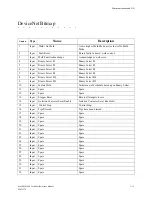
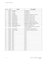
Page 49: ...16 9 Input Binary Select 32 Binary Select 32 10 Input Initiate Weld Initiates a weld schedule based upon Binary Select 11 Input Spare Spare 12 Input Spare Spare 13 Input Stepper Reset Resets all step...

Page 50: ...ld schedule has completed 11 Output Weld in Progress Indicates that a weld is currently in progress 12 Output Steppers are Reset Indicates that all steppers are reset 13 Output Stepper Approaching Max...

Page 51: ...For more details refer to the drawing package provided with your control BINARY SELECT 1 Input BS1 BINARY SELECT 2 Input BS2 BINARY SELECT 4 Input BS4 BINARY SELECT 8 Input BS8 BINARY SELECT 16 Input...

Page 52: ...VALVE 1 ADVANCE Fluid VALVE 1 Output VLV1 VALVE 2 ADVANCE Fluid VALVE 2 Output VLV2 VALVE 3 Output VLV3 VALVE 4 Output VLV4 VALVE 5 Output VLV5 VALVE 6 Output VLV6 RETRACT VALVE 1 RV1 RETRACT VALVE 2...

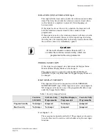
Page 53: ...ailable for use in programming a weld schedule What is a Weld Schedule A weld schedule is a list of commands that the control is to execute For example to perform a simple spot weld you might use a we...

Page 54: ...al process control SPC functions Selecting the firing mode to assure consistent voltage or to assure constant secondary current Pausing in a schedule to wait for certain operating conditions to become...

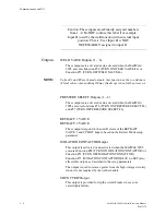
Page 55: ...RM TIME 20 WELD nn CY IMP mm I 21 TEMPER nn CY IMP mm I 22 PREHEAT nn CY IMP mm I 23 POSTHEAT nn CY IMP mm I 24 PRE WELD nn CY IMP mm I 26 WELD nnnn MSEC mm I 30 WELD nn CY IMP nnnn0 AMPS 31 TEMPER nn...

Page 56: ...OFF WELD COMPLETE 65 ISOLATION CONTACTOR DELAY nn SEC 75 EXTEND UNTIL NO INITIATE 76 SEC CURR LIMITS HI nnnn0 Low nnnn0 81 TRANSFORMER TURNS RATIO nnn 1 nnn 1 256 82 LINEAR STEPPER nn ASSIGNED 0 OFF...

Page 57: ...P mm I 21 TEMPER nn CY IMP mm I 22 PREHEAT nn CY IMP mm I 23 POSTHEAT nn CY IMP mm I 24 PRE WELD nn CY IMP mm I 26 WELD nnnn MSEC mm I 30 WELD nn CY IMP nnnn0 AMPS 31 TEMPER nn CY IMP nnnn0 AMPS 32 PR...

Page 58: ...PLETE 65 ISOLATION CONTACTOR DELAY nn SEC 75 EXTEND UNTIL NO INITIATE 76 SEC CURR LIMITS HI nnnn0 Low nnnn0 81 TRANSFORMER TURNS RATIO nnn 1 nnn 1 256 82 LINEAR STEPPER nn ASSIGNED 0 OFF 85 PROCESS WE...

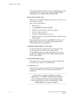
Page 59: ...g F1 01 SQUEEZE nn CYCLES 02 COOL nn CYCLES 03 HOLD nn CYCLES 04 OFF nn CYCLES 05 INITIAL SQUEEZE nn CYCLES 06 QUENCH nn CYCLES 07 WAIT nn CYCLES 08 PRE COMPRESSION 09 GUN WAIT DELAY 10 DELAY 11 PLATE...

Page 60: ...function shown in function numbers 20 26 use Automatic Voltage Compensation Functions using the AVC firing mode specify weld current as nn I when firing in cycles or mm I when firing in milliseconds r...

Page 61: ...Weld Data display Weld Functions Using Automatic Voltage Compensation 20 WELD nn CY IMP mm I 21 TEMPER nn CY IMP mm I 22 PREHEAT nn CY IMP mm I 23 POSTHEAT nn CY IMP mm I 24 PRE WELD nn CY IMP mm I 26...

Page 62: ...P nnnn0 AMPS 32 PREHEAT nn CY IMP nnnn0 AMPS 33 POSTHEAT nn CY IMP nnnn0 AMPS 34 PRE WELD nn CY IMP nnnn0 AMPS 35 MAXHEAT nn MS BELOW nnn us nnnn0 AMPS 36 WELD nnnn MSEC nnnn0 AMPS 37 CHC WELD nn CY n...

Page 63: ...S This function is used when welding special insulated metals or quiet steel metals The function MAXHEAT is a preheating function used to breakdown the insulating properties of the material between th...

Page 64: ...trol to fire one cycle at 65 of the maximum available heat Then over the next 29 cycles gradually decrease the heat provided to 45 42 PRESLOPE 30 CY 45 I TO 65 I tells the control to fire one cycle at...

Page 65: ...indicate the weld control will pulsation weld Pulsation welding provides a specified number of impulses An impulse is a number of heat cycles when weld current flows followed by a number of cycles wh...

Page 66: ...s currently in progress 59 TURN OFF WELD IN PROGRESS The control turns this output OFF when a weld in progress has com pleted 60 IMPULSE 10 HEAT CY 10 COOL CY This function defines the length of a wel...

Page 67: ...utput under the following conditions a fault occurs AND the BINARY SELECT or WELD INITIATE input is still active 65 ISOLATION CONTACTOR DELAY SEC 0 99 This parameter tells the control how long to hold...

Page 68: ...schedule the appropriate stepper is advanced incremented each time you execute the weld schedule If Function 82 is used in a weld schedule it MUST be the first function in the schedule Valid stepper n...

Page 69: ...eld data collected 99 GOTO SEQ nn nn 1 99 This function is an unconditional jump to another weld schedule It tells the control to stop the present weld schedule and continue with the first function in...

Page 70: ...welding machine Sequences 1 15 default to this sequence Sequences 16 31 are defaulted to blank START OF SEQUENCE nn 82 LINEAR STEPPER 0 ASSIGNED 0 OFF 76 SECONDARY CURRENT LIMIT HIGH 99999 LOW 00000...

Page 71: ...and the actual value of current that would be produced A change in C Factor will indicate changes in the welding environment The MedWeld 5000 calculates the actual C Factor after every weld The progra...

Page 72: ...er to the discussion of C Factor on page 7 1 The target current is determined by the firing mode used by the weld function I or automatic current compensation This calculation is shown below AVC Targe...

Page 73: ...iring mode the target value is established by the following calculation Target current A in Function 30 Stepper boost An example of how these calculations are used is shown below Function 30 is WELD 0...

Page 74: ...an example Car Type 1 Weld Schedule 20 SET SPC OFFSET TO 01 Weld Schedule 01 15 Welds Made Bins 1 15 Weld Schedule 02 15 Welds Made Bins 16 30 Weld Schedule 03 18 Welds Made Bins 31 48 Car Type 2 Wel...

Page 75: ...n It is intended for special situations such as tear down which require continuous data collection SPC setup Parameters DATA COLLECTION SAMPLE SIZE 05 1 99 DATA COLLECTION SAMPLE FREQUENCY 0100 1 9999...

Page 76: ...ged for retrieval Data uploaded 3 8 Data collected Data ignored 4 8 Data collected Data ignored 5 8 Data collected Data ignored 6 8 Data collected Data ignored 7 8 Data collected Data ignored 8 8 Data...

Page 77: ...ive For air only and OHMA cylinders the HIGH state of the RETRACT PILOT input s indicates the partially closed position The LOW state indicates the fully open position LATCHED tells the control to cha...

Page 78: ...s set to ALLOW If the weld schedule does NOT contain this function the control will allow you to execute a sequence with the gun in the full retract position DEP 100S Programming Restrictions The soft...

Page 79: ...alf cycle It is during this half cycle that the inductance of the transformer is overcome If setting the FIRING MODE to PRI CURRENT or FIRING MODE to PRI VOLTAGE in the setup parameters the secondary...

Page 80: ...he inverter can deliver more voltage or current if necessary If the on time is less than 406 sec the inverter can deliver more voltage or current If the on time is 406 sec and more voltage or current...

Page 81: ...f the software also inhibits the ability to turn the stepper on or off The software in the MedWeld 5000 does allow the stepper to be advanced or reset as needed See the chapter on Steppers for more in...

Page 82: ...Advanced Software Features 5 12 MedWeld 5000 Technical Reference Manual M 032170...

Page 83: ...T tells the control to turn OFF the NO FAULT output or turn ON the FAULT output This indicates that a fault condition was detected Fault conditions normally inhibit initiation of a weld schedule ALERT...

Page 84: ...s have changed state while the processor is repeating WELD INITIATE NOT PRESENT FAULT ALERT NONE If the weld schedule is using the function to TURN ON WELD COMPLETE the MedWeld 3005 expects the INITIA...

Page 85: ...the weld and performed an unsuccessful reweld If the schedule contains the function REWELD IF LOW CURRENT LIMIT FAULT this indicates that the control performed a reweld and the desired current was pr...

Page 86: ...it is exceeded the weld schedule is finished in No Weld Mode The control generates a HEAT CYCLE LIMIT fault WELD PROCEED FAULT ALERT NONE This fault is generated if the appropriate WELD PROCEED input...

Page 87: ...Limit is reached on 4 or more consecutive high frequency half cycles WELDING TRANSFORMER FAULT This fault is generated when either six or more consecutive half cycles or more than four consecutive mi...

Page 88: ...kage is open NOT field replaceable SEC CURRENT SENSOR FAULT ALERT When operating in the SEC CURRENT firing mode this fault occurs when the inverter detects a shorted malfunctioning or otherwise defect...

Page 89: ...inations of weld transformer and secondary load TRANSFORMER TURNS RATIO 1 nnn 1 256 This parameter tells the control the turns ratio of the welding transformer used so that the control can determine t...

Page 90: ...the I firing mode PULSE WIDTH LIMIT The output power level is determined by controlling the pulse width of the high frequency square wave This setup parameter will let the operator set the limit of th...

Page 91: ...the high current window as a percentage boost over the current expected The low current window is a percentage decrease from the expected current The expected current is the base current programmed i...

Page 92: ...E In constant velocity mode this is the maximum speed reached by the gun as it approaches the soft touch position VELOCITY OF SOFT TOUCH When switched to force control mode this is the maximum speed r...

Page 93: ...ULT CONTROL IN NO WELD ALERT INITIATION ON POWER UP FAULT NO WORK DETECTED FAULT LOW HEAT DETECTED FAULT WIRE BREAK DETECTED FAULT LOW POWER LINE FAULT SOFT OVER CURRENT FAULT CURRENT REGULATION LIMIT...

Page 94: ...SEAM 60 CYCLES ISOLATION CONTACTOR DELAY 5 SEC HIGH CURRENT LIMIT WINDOW 20 LOW CURRENT LIMIT WINDOW 20 DATA COLLECTION SAMPLE SIZE 5 DATA COLLECTION SAMPLE FREQUENCY 100 TRANSFORMER TURNS RATIO 100 1...

Page 95: ...the schedule You can program up to 63 linear steppers The following sections describe the linear stepper type along with directions on how to program the stepper You can assign a stepper to a group T...

Page 96: ...r other programming device to assign steppers to a group For example if one gun tips was used to several different schedules using different steppers grouping allows you to automatically increment the...

Page 97: ...s use this profile by default START OF STEPPER STEP 1 00 i 0700 AMPS IN 0060 WELDS STEP 2 00 i 0700 AMPS IN 0180 WELDS STEP 3 00 i 0700 AMPS IN 0300 WELDS STEP 4 00 i 0700 AMPS IN 0600 WELDS STEP 5 00...

Page 98: ...he step count the number of welds completed during the present step From the stepper status display Press F1 to see a different stepper Press F3 to advance the stepper Press F4 to see the stepper sett...

Page 99: ...n the control detects a Fault condition it may inhibit welding or inhibit initiation of a new schedule until the fault condition is cleared Alert conditions serve more as a warning of a potential prob...

Page 100: ...HIGH C FACTOR SYSTEM COOLING HEAT CYCLE LIMIT WELD PROCEED CONTROL IN NO WELD INITIATION ON POWER UP PRESSURE SWITCH NO WORK DETECTION LOW HEAT DETECTION WIRE BREAK DETECTION BREAKTHROUGH LOW LIMIT BR...

Page 101: ...NTROL STOP input normally HIGH dropped out The CONTROL STOP input from the ROBOT or PLC was not active when the control tried to initiate a weld Check repair ladder logic Note if the Control Stop mess...

Page 102: ...in current measurement certain failures in the timer unit may cause this fault to occur Secure the cable that runs between the inverter and the timer unit Check for bad con nector Replace as necessar...

Page 103: ...ule due to insufficientsecondary current during a weld Low current limit is set too high Re program the Low Current Limit setup parameter Unusual condition in the secondary Check for improper part fit...

Page 104: ...causing the fault Check fuses and replace as necessary The solid state relay is faulty Replace relay The instruction to activate the isolation contactor was exe cuted but the control was unable to pul...

Page 105: ...unction 92 Unusual conditions in the secondary Check for worn cables loose connections low air pressure or other causes of decreased sec ondary current The Low C factor limit was programmed too high L...

Page 106: ...part to weld or tip to tip weld Place the proper work piece to be welded in the welding inter face LOW HEAT DETEC TION CHC This is only used when using CHC and repersents that there was not enough en...

Page 107: ...elding sequence and the ontime level is above the breakthrough limit before blanking time is over Breakthrough limit is set to high Too much sealer used on the part which would bring the ontime above...

Page 108: ...quested current programmed cur rent plus any additions from stepper program during three or more con secutive mid frequency half cycles NOTE This fault is not generated at the beginning of a weld to a...

Page 109: ...for shorted or damaged cables Check weld transformer for Internal short circuits Short circuits to ground Defective secondary diodes DRIVER LOW VOLTAGE The inverter detected a failure in one or more I...

Page 110: ...open circuited This condition is not checked if set to NONE Check continuity of secondary current sensor circuit if used Replace sec ondary current sensor if defective Set this condition to NONE if no...

Page 111: ...trol transformer Check the control circuit breaker Verify 480 600 VAC is present in incoming lines Verify that operator handle is UP to turn ON the breaker No 24 VDC VAC at the timer assembly Check th...

Page 112: ...Monitor the line power to chassis power for possible transient or shorting Replace power supply Processor not in Run Mode All processor LEDs are functioning normally Improper mode selected Verify the...

Page 113: ...own Line power is not con nected to the power supply Verify that line power is connected to the power supply Improper voltage jumper setting Check the jumper setting to verify that it matches the inpu...

Page 114: ...power supply and that external 120 VAC is connected Faulty DEP 100S WTC timer or Network Power Pack Replace as necessary Incorrect network address for weld control Verify the welder ID and network add...

Page 115: ...ck the following Primary transformer cables grounded SCR breaking over at low potential or shorted Inverter is faulty Replace inverter assembly Circuit breaker is faulty Replace circuit breaker Circui...

Page 116: ...k the timer module and the input supply voltage to the timer module Check the I O Status Display at the DEP Control is in retract and the setup parameter specifies that initiation is INHIBITED from re...

Page 117: ...e as necessary Control sequences without firing The control is in No Weld Check the status of the WELD NO WELD input Verify that the control and all data entry devices are in Weld mode A fault occurre...

Page 118: ...ate relay If the control is externally powered one of the internal control transformer fuses may be blown Check fuses Replace as necessary The control was unable to pull in the isolation contactor due...

Page 119: ...at L1 and L2 Faulty circuit breaker Supply voltage IS connected to the breaker Verify that power is available on the load side of the circuit breaker Faulty cable between timer and inverter Replace ca...

Page 120: ...Hardware Troubleshooting 9 10 MedWeld 5000 Technical Reference Manual M 032170...
Reviews: