Manual MRIK3-C EN
Woodward
DOK-TD-MRIK3-C Rev. A
17
4.4
Front plates (for -ER/-XR-relay types)
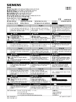
Figure 4.8: Front plate MRIK3-ICER MRIK3-ICXR
The LEDs I
P
, I
Q
, RS and FR on the MRIK3-ICE and
MRI3-ICE emit a yellow light, all other LEDs are bi-
coloured. The LEDs at the left next to the alphanumeri-
cal display give a green light during measuring and a
red one when a fault signal occurs.
The LEDs underneath the <SELECT/RESET> - push
button emit a green light during adjustment and inquiry
of the setting quantities left to the LEDs. They show a
red light if the printed setting quantities right to the
LEDs are activated.
4.4.1 Indicating
LEDs
L1, L2, L3
Indication of the phase currents
E
Indication of the earth current
Date and time
green: forward direction; red: reverse
direction
I
P
Indication of the active component of
the earth fault current
I
Q
Indication of the reactive component
of the earth fault current.
FR
Parameter for the fault recorder
RS
Setting of the relay address
4.4.2 Adjusting
LEDs
I> Overcurrent
setting
I>>
Short-circuit
setting
IE>
Earth overcurrent setting
IE>>
Earth short circuit setting
CHAR
Selection of characteristics lights in
combination with all time delay
settings.
DI
Assignment of the input functions to
the
digital
inputs
Trip
ext.
tripping
SHOT
Number of AR shots
tF
max. fault time
tD1
dead time before 1. AR
tD2
dead time before 2. AR
tD3
dead time before 3. AR
tD4
dead time before 4. AR
tCl
max close impulse time
tR reclaim
time
FR
Parameter for the fault recorder
RS
Setting of the relay address
P2
Parameter set 2 is active
CB red
CB is switched on
CB green
CB is switched off
CB blinking
CB has faults


