1143200
SmartPAC PRO Installation Manual
30
Chapter 2 – Installing SmartPAC PRO
To install a new DiProPAC or ProCamPAC board, do the following:
1.
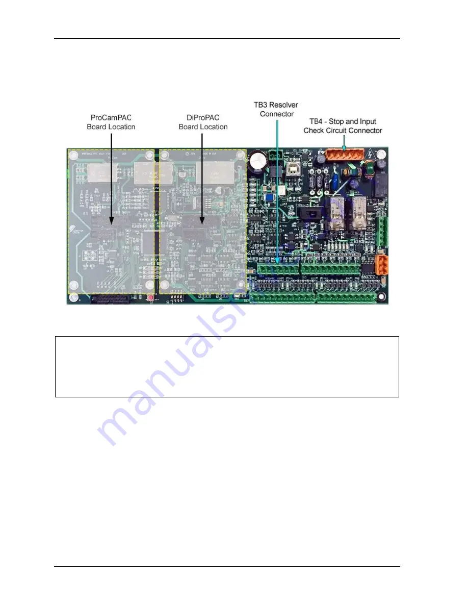
On the SmartPAC PRO board, locate the connector in which the new board should be installed
(see Figure 2-8).
Figure 2-8
. SmartPAC PRO Main (RTS) Board showing option module boards and TB3 and
TB4
CAUTION
DAMAGE TO BOARD FROM STATIC DISCHARGE
Ground yourself before touching circuit boards or chips by touching a large metal object such as
the press. Static electricity can destroy electronic components.
Failure to comply with these instructions could result in property damage.
2.
Making sure that you are grounded, install the new board by plugging it into the appropriate
connector. Connectors are keyed, so you can plug in the boards in only one direction.
3.
When the board is properly seated, screw it down to the four standoffs, using the screws that
came with the kit.
4.
Remove the connector(s) from the board, one connector for an 8-sensor or 8-cam unit, two
connectors for a 16-sensor or 16-cam unit, four connectors for a 32-sensor unit. Terminal block
assignments for these different boards are as follows:
•
DiProPAC 8: Sensors 1-8 to TB554
•
DiProPAC 16: Sensors 1-8 to TB554, sensors 9-16 to TB554
•
DiProPAC 32: Sensors 1-8 to TB554, sensors 9-16 to TB554, sensors 17-24 to TB555, and
sensors 25-32 to TB555
Summary of Contents for SmartPAC PRO
Page 2: ......
Page 4: ......
Page 10: ......
Page 12: ......
Page 14: ......
Page 52: ...1143200 SmartPAC PRO Installation Manual 52 Chapter 2 Installing SmartPAC PRO ...
Page 64: ...1143200 SmartPAC PRO Installation Manual 64 Chapter 8 SmartPAC PRO Fault Messages ...
Page 66: ......
Page 68: ......
Page 70: ......
Page 72: ......
Page 74: ......
Page 75: ......
Page 76: ......
Page 77: ......
Page 78: ......
Page 79: ......
Page 80: ......
Page 81: ......
Page 82: ......
Page 83: ......
Page 84: ......
Page 85: ......
Page 86: ......
Page 87: ......
Page 88: ......
Page 89: ......
Page 90: ......
Page 91: ......
Page 92: ......


