4-18
n
Vesta Gas and Electric Slide-In Ranges
DIAGNOSTICS & TROUBLESHOOTING
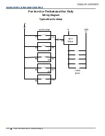
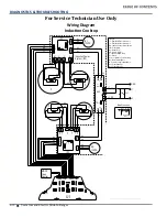
For Service Technician Use Only
Wiring Diagram
Induction Coo to
©2014. All rights reserved.
W10665236A
NOTE:
This sheet contains important Technical Service Data.
FOR SERVICE TECHNICIAN ONLY
DO NOT REMOVE OR DESTROY
FOR SERVICE TECHNICIAN’S USE ONLY
Wiring Diagram
Do Not Remove Or Destroy
W10665236A
3/14
Quick Connect Plugs
Control Wiring Diagram
Cooktop Wiring Diagram
For controls
NOTE:
Schematic shows oven door open and elements off.
P5 (Blue)
BK/
WH
OR
P7 (Black)
RD
RD/
WH
P10 (Yellow)
WH
P2 (Red)
BK
YL
P1 (Blue)
P15 (Natural)
P4 (Green)
BU
V
BK
P6 (Red)
BK
GY
YL
RD
RD
BK YL
BK
V
V
BK
1
1
1
1
1
1
1
1
P3 (Yellow)
BK
1
OR/
WH
GY GY
L1
L2
N
Oven Control MRC2
Convect (K2)
Oven Light (K6)
Convect Fan (K7)
Cooling Fan (K9)
Broil (K5)
DLB (K13)
Bake (K4)
Power Supply
P6-1
P1-3
P6-3
P2-3
P4-2
P15-1
P15-2
P1-4
P7-5
P7-4
P10-4
P10-3
P5-1
P7-3
P7-7
P5-4
P5-3
P7-1
P5-9
P4-1
P2-1
BK
Thermofuse
Opens at 363˚F
(184˚C)
BK
BK
BK
BK
Bake 3600W
Broil 4000W
Cooling Fan
Main Oven Temp Sensor
Convection 3200W
GND
Signal
5 VDC
Oven Light 40W
Convect Fan
BK/WH
BK
WH
WH
WH
WH
WH
BU/WH
RD
RD
RD
RD
GY
V
V
V
OR
RD/WH
RD/WH
BU
YL
YL
YL
Hall
Effect
Sensor
BK
P3-2
Bake Drawer (K1)
WH
Bake Drawer 1200W
OR/WH
P3-1
Door Position Switch
M
M
Main Connection
2
L1 L1
L1
L2 L2
L2
G
208 - 240V
60Hz
BL
12VDC
I1
BR
12VDC
S
+
_
L
N
J205
J1
T3B
T3A
J806
J605
J604
T2A
T2B
1
5
J801
GF801
J802
J803
L
N
J1
EMI
W
L
N
J2
S1
S1
S
+
_
L
N
Mo
.B
F1
F2
fuse 2
J008
J004
J003
J002
J005
J007
J006
J001
5
MRC2
Oven
Control
UI
L1
L1
L2
L2
BK
LB
WH
RD
YL
BU
RD
BK
BU
BR
BU BR
BU BR
BU
BR
BU
RD
BK
CONNECTOR NOTE:
J007 - Service
connector (SAM)
(manufacturing only)
J003 - WIDE 2 connector
from IPC2
J004 - WIDE 1 connector
from IPC1
J806 - UI
connector
J604/J605 -
Coil thermistor connector
J205 -
Blower connector
T3A/T3B/T2A/T2B -
Induction
coil connector
J801 - MCU connector
(for factory
programming only)
GF801 - “SAM”
Service connector zone
(manufacturing only)
7
6
5
4
J008 - WIDE 3 connector
from MRC2
fuse 1
Induction Power
System (IPS)
IPC
L1 BK
L2 RD
Cx2 Cx1
GND
L1
L2
4
3
2
BK
BK
BK
BK
I1
I1
I1
BK
LB
WH
RD
YL
S1
S1
BK
BK
BK
BK
1
5
4
3
2
J205
J1
T3B
T3A
J806
J605
J604
T2A
T2B
J801
GF801
J802
J803
IPC
Mo
.A
Mo
.
Mo
.
1
1
2
2
Mo
.
Mo
.
Mo
.
Mo
.
1
1
2
2
4
3
2
1
5
4
3
2
1
5
4
3
2
1
Legend:
J1 - Filter Main Power Connector 1
J2 - Filter Main Power Connector 2
IPC - Induction Power Control Board
EMI - Filter Board
BL - Blower (Left)
BR - Blower (Right)
I1 - Inductor (Single Zone)
S1 - Sensor
UI - User Interface (Touch Control)
W1 - Main Terminal Block
W - Power Housing Terminal Block
Cx1 - Filter Capacitor
Cx2 - Filter Capacitor
LEGEND
Indicator Light
Thermistor
Non-resettable Fuse
Connection
No
Connection
On Some
Models
In Line
Connection
Connector P2,
Position 1
Circuitry
Enclosed Within
Terminals
D
Single
Switch
Thermal Switch
(opens on heat rise)
Thermal Switch
(closes on heat rise)
Resistor or
Element
Motor
Incandescent
Light
P2-1


