DIAGNOSTICS & TROUBLESHOOTING
Vesta Gas and Electric Slide-In Range
n
4-13
For Service Technician Use Only
FOR SERVICE TECHNICIAN’S USE ONLY
22
Component Testing Chart
To check for proper voltage, complete the following steps:
1.
Unplug range or disconnect power.
2.
Connect voltage measurement equipment.
3.
Plug in range or reconnect power and confirm voltage reading.
4.
Unplug range or disconnect power after performing voltage
measurements.
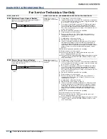
Location On the Cooktop
Checkpoints
Results Voltage
EMI filter board
J1 - BR - BU
From 208VAC to 240 VAC - 60Hz
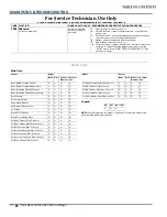
Induction Power Control (IPC): Left and right
J1 - BR - BU
From 208VAC to 240 VAC - 60Hz
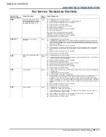
Induction Power Control (IPC) to blower fan: Left and right
J205 - (BK) - (R)
J205 - (BK) - (BU)
From 0VDC to 12VDC
Induction Power Control (IPC) to the element sensor: Left
and right
J604 - (1) - (2)
J605 - (1) - (2)
+5VDC
0V
+10.5V
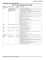
Induction Power Control (IPC) to the User Interface
J806 - BK - 1
+5VDC
J806 - LT BU - 2
WIDE_DATA
J806 - W - 3
Ground
J806 - R - 4
Standby
J806 - Y - 5
+10VDC


