background image

Lync AEGIS Controller


8: APPENDIX D  

L-OMM-013_A   

•    4/20/2022Technical Support  •  (800) 433-5654  •  Mon-Fri, 8 am - 5 pm EST 

 74 

 of 

100 

  press the OK key to confirm changes and close the set point screen. 


In the differential temperature windows (parameters ST04 

– ST07): 


  press the UP key to increase the value by 0.1°C (32.1°F); 

  long press the UP key to increase the value by 1°C (33.8°F); 

  press the DOWN key to reduce the value by 0.1°C (32.1°F); 

  long press the DOWN key to reduce the value by 1°C (33.8°F). 

  press the BACK key to close differential adjustment screen without confirming changes; 

  press the OK key to confirm changes and close the differential adjustment screen. 


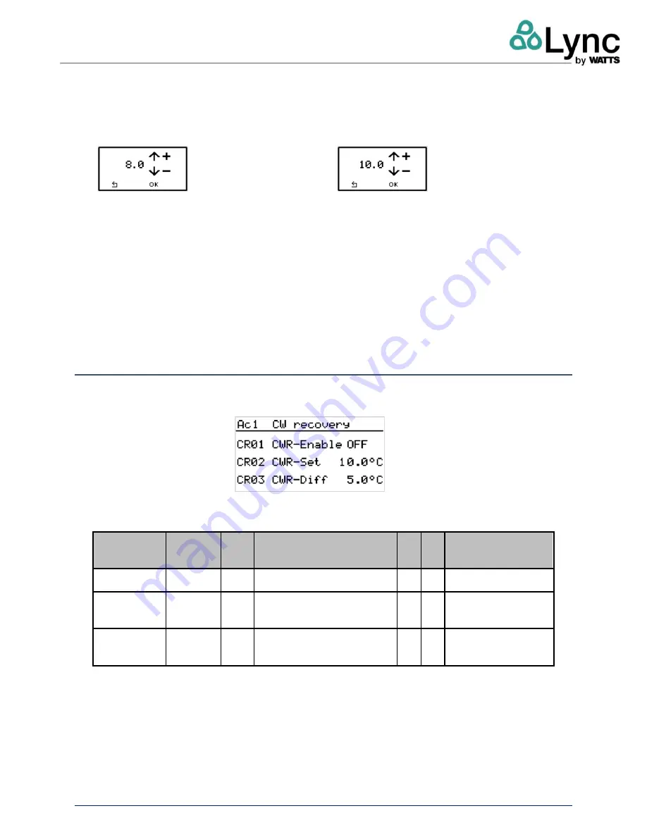
8.9.9. MENU - AC CW RECOVERY (COOL RECOVERY) 

On the A.Settings menu, with the c.CW RECOVERY menu selected, press the RIGHT key to 
access the cold recovery function setting screen. 

Select the following parameters with the UP and DOWN keys: 


Modbus  
address


Read 
Write


Code


Meaning


Min


Max


Unit of 
measurement 

9638 

RW 

CR01 Enable cold water recovery OFF


ON


16807 

RW 

CR02 Cold water recovery set 

point 

-30  50  °C 

16808 

RW 

CR03 Cold water recovery 

differential 

30  °C 


When the parameter is selected, press the OK key to access the window where it can be edited. 


In the function enable/disable window (parameter CR01): 


Summary of Contents for Lync AEGIS

Page 1: ...rial including but not limited to implied warranties of merchantability and fitness for a particular application Lync is not liable for errors appearing in this manual nor for incidental or consequential damages occurring in connection with the furnishing performance or use of these materials L OMM 013_A 4 20 2022 Engineered Solutions Lync 425 W Everman Pkway St 101 Fort Worth TX 76134 USA T 817 3...

Page 2: ...2 2 4 On Off Command 13 2 5 Led Bar 15 2 6 Unit Main Info 15 2 6 1 Unit Main Info 1 Ref Circuit Hot Side and User Water Side 16 2 6 2 Unit Main Info 2 Superheating 17 2 6 3 Unit Main Info A W Configuration Source Side 17 2 6 4 Unit Main Info Cold Recovery Option Source Side 18 2 6 5 Unit Main Info Water Source Side 19 2 7 Setpoint Menu 19 2 8 Main Menu 22 2 8 6 Main Menu Unit Variables 23 2 8 7 Ma...

Page 3: ...bus 46 3 9 Control Panel 47 3 10 Logout 47 4 APPENDIX A INTERNAL CONTROL SPECIFICATIONS TECHNICAL DATA 49 5 APPENDIX B TOUCH SCREEN ELECTRICAL CONNECTIONS 54 6 TECHNICAL SPECIFICATIONS 55 7 APPENDIX C ACCESS TO THE WEB SERVER 57 7 1 Ethernet Connection 57 7 1 3 Ethernet Port 57 8 APPENDIX D 64 8 1 Operation With Built In Display 64 8 2 General Information 64 8 3 Key Function 64 8 4 Menu Navigation...

Page 4: ...ET 84 8 9 20 MENU H SERVICE 84 8 9 21 MENU I MANUFACTURER 84 8 10 Service Menu 85 8 10 1 Menu St Set Point 86 8 10 2 MENU RC Remote control 86 8 10 3 Menu Ai Anti Freeze 86 8 11 Hot Side Anti Freeze 88 8 12 Cold Side Anti Freeze Recovery Source 90 8 12 4 MENU MD RS485 1 Config 90 8 12 5 Menu Et Ethernet 93 8 12 6 Menu Df Defrost 94 8 12 7 Df01 0 Defrost At A Fixed Evaporation Temperature 94 8 12 8...

Page 5: ...epend on plant engineering choices and must not be changed in any way except by expert personnel The unit can be controlled in three ways 1 Directly via the built in display on the main electronic controller 2 Via remote terminal touch screen 3 Via web interface via local network or remote VPN connection The three control methods are equivalent however there are different levels of access through ...

Page 6: ...temperature in the storage tanks Please note that the delivery temperature is regulated by modulating the pump therefore the flow of hot water at the outlet is not constant 1 3 Sequence Of Operation The hot water storage tanks used in this heating system must be equipped with the two provided temperature sensors or other sensors meeting requirements for a NTC 10k sensor The optional BT2 sensor hot...

Page 7: ...the temperature BT1 remains below the Set point unit OFF value ST03 Once BT1 reaches Set point unit OFF the unit will be turned off To limit the possible discomfort that can be generated by excessive heat dissipation the probe BT2 may be used to operate a comfort function In this case even if the temperature BT1 is higher than the value of Set point unit OFF the unit operate when the BT2 is lower ...

Page 8: ...h as a central chilled water system See Aegis Electronic Controller Manual L OMM 013 for further details on how to activate and control this function NOTE This option is available only for the Air source unit 1 5 Domestic Hot Water Pump Management The software also manages the domestic hot water pump The start minimum and maximum speed can be adjusted separately for both pumps The domestic hot wat...

Page 9: ...e efficiency and at the same time avoid too high temperatures to the compressor the target superheat value is not constant but will be adjusted according to the compressor discharge temperature and compressor oil temperature This superheat limit should not be changed by a user except under direction from the manufacturer or an authorized manufacturer s representative 1 7 High Inlet Temperature Hit...

Page 10: ...onella depends on the water temperature As can be seen from the chart below the disinfection is feasible through thermal shock Figure 1 4 Legionella Growth Chart1 The anti Legionella function raises the water storage tanks to a high temperature and subsequently circulates to ensure complete disinfection of the system The anti Legionella function if enabled via ALG01 Enable anti Legionella is activ...

Page 11: ... least the ALG09 Phase 1 set BTL default 131 F 55 C 1 9 2 PHASE 2 The Anti Legionella active relay contact remains closed The Anti Legionella phase 1 completed relay contact is closed At the end of phase 1 the compressor switches off while the secondary pump is brought to a fixed speed ALG11 Unit phase 2 pump set until the BTL probe reaches the ALG09 Phase 2 set BTL e g 70 C The anti Legionella cy...

Page 12: ...ration This application gives the user an overview of the main parts and controls of the machine visualization of the setpoints the status of the main devices and the control of the unit mode without needing to open the unit electrical cabinet In order to communicate with the main control the touch interface is connected through the RS485 2 serial port with the Modbus RTU protocol with a baud rate...

Page 13: ...Main Menu and Homepage 2 Unit status 3 Compressor status 4 Primary water pump status 5 Outlet water temperature 6 Set point regulation 7 Unit Main Info 8 On Off command 9 Input Output list 10 Inlet water temperature 11 Alarms and warnings page 12 Date and time 2 4 On Off Command The ON OFF command is accessible from the homepage by pressing the icon ...

Page 14: ... thermostats to switch the unit ON and OFF please access to the unit web server see previous section press the REMOTE CONTROL button located in the central area of the main screen and set the parameters as follows The RC01 Remote control parameter needs to be enabled and RC03 Thermal request by set to Supervision It will be still possible to use the internal web server to switch the unit ON OFF th...

Page 15: ...en of is in stand by mode Three colors are used to identify the unit s status Green The unit is on and running White The unit is on and in stand by mode Red blinking There is an alarm or warning active 2 6 Unit Main Info Detailed unit information is accessible from the homepage by pressing the icon Click on the unit main info icon to see the screens showing the details about the current unit statu...

Page 16: ... Legend 1 Refrigerant high pressure discharge temperature 2 Low pressure suction temperature 3 Compressor oil temperature 4 Compressor status On Off 5 Refrigerant temperature after gas cooler 6 Utility hot water inlet 7 Primary water pump speed in percentage 8 Secondary water pump speed in percentage optional selectable 9 Secondary side water temperature optional selectable 10 Utility hot water ou...

Page 17: ...heating 1 Oil valve status 2 Electronic expansion valve opening status percent 3 Superheating temperature 4 Evaporation temperature 5 Refrigerant temperature after gas cooler 6 Refrigerant low pressure temperature before gas cooler 2 6 3 Unit Main Info A W Configuration Source Side 1 Source water inlet temperature 2 Condenser fan speed percent 3 Coil pack temperature ...

Page 18: ... 5 Defrost central phase percent 6 Drop off phase percent 7 Waiting phase percent 2 6 4 Unit Main Info Cold Recovery Option Source Side 1 External air temperature 2 Source cold water inlet 3 Source water pump status On Off 4 Source cold water outlet 5 Recovery system status 6 Coil pack temperature 7 Fan speed in percentage 8 Defrost phase info 9 Subcooling temperature ...

Page 19: ...Main Info Water Source Side 1 Source inlet water temperature 2 Source pump water status On Off 3 Coil pack temperature 4 Subcooling temperature 2 7 Setpoint Menu It is possible to modify the unit set points by pressing the Set icon from the homepage The user can set both the delivery water Hot water set point and the tank temperature sets BT1 and BT2 ...

Page 20: ...be on the last hottest tank 5 Set point of the temp probe on the last hottest tank 6 Temperature differential band of the probe on the second tank Please note that the Hot water set point doesn t directly influence the compressor ON OFF status The delivery temperature is regulated by modulating the primary side pump therefore the flow of hot water at the outlet is not constant If the outlet temper...

Page 21: ...ri 8 am 5 pm EST 21 of 100 The set points BT1 and BT2 are referred to probes placed in the tanks The BT2 sensor hot side probe is located in the top of the last storage tank in the series near the supply outlet The BT1 sensor cold side probe is located in the bottom of the first storage near cold return connection ...

Page 22: ...EN L OMM 013_A 4 20 2022Technical Support 800 433 5654 Mon Fri 8 am 5 pm EST 22 of 100 2 8 Main Menu The display main menu is accessible from the homepage by pressing the icon 1 Unit menu 2 Display settings 3 Reset alarms and parameters 4 Regulation menu ...

Page 23: ...23 of 100 2 8 6 Main Menu Unit Variables Here the user can manage the values of the anti ice function on the heat exchangers and the values of the water pump on the secondary side 1 Anti ice hot side management 2 Anti ice cold side management 3 Cold side temperature differential band set 4 Defrost 5 Secondary water pump management ...

Page 24: ...0 2022Technical Support 800 433 5654 Mon Fri 8 am 5 pm EST 24 of 100 2 8 7 Main Menu Display Settings In the display settings it is possible to select the unit of measure and set the date time The other options are reserved Unit of measure selection Date and time settings ...

Page 25: ...ri 8 am 5 pm EST 25 of 100 2 8 8 Main Menu Initialization In this menu it is possible to reset the alarm history The Reset to factory settings command is reserved to users with Administrator access level In this page the user can reset the alarm history 1 or reset all the variables values to the factory defaults 2 ...

Page 26: ...the bell in the upper right corner The Reset alarms and Alarm history functions will be also available Here the user can read and restore those alarms that do not automatically reset with the related command 1 and access alarm history page 2 2 9 2 Alarm History In Alarm history both the activation START and reset STOP times of past alarms are stored Here the user can read old alarms and understand...

Page 27: ...lt is 192 168 1 160 please refer to Appendix C if you need to change your PC s IP address accordingly You will be prompted for the credentials Use the username user and the password 1 to access with the lowest authorization level Please refer to the User management section later on for additional details about the user access levels After successful authentication the unit main screen will be disp...

Page 28: ... Mon Fri 8 am 5 pm EST 28 of 100 The unit probe values visible in the central area are updated in real time both C bar and F psi unit of measure are supported The operation of the compressor and the fans are displayed with animated icons The hot water storage tank system is shown as a generalized single tank ...

Page 29: ... software or touch screen to switch the unit ON and OFF please press the REMOTE CONTROL button located in the central area and set the parameters as follows RC01 Remote control ENABLED RC03 Thermal request by Supervision Now it is possible to use the RC02 Heat pump ON OFF switch to enable or disable the unit 3 1 3 Unit On Off Management Via Web Server The status of both the ON OFF request and the ...

Page 30: ...e placed in MAN position The hot water demand Thermal request can be initiated by the user via web server or still controlled via dedicated digital input e g connected to an external mechanical thermostat or PLC as shown in the next paragraphs 3 1 4 Unit On Off Via Web And External Thermal Request In order to use the web interface combined to an external mechanical thermostat or PLC switch the uni...

Page 31: ...OFF Digital input 2 of the controller needs to be closed by an external thermostat or PLC device as well in order to activate the unit 3 1 5 Main Menu The main menu is located on the left side of the web interface main screen Click on the menu to enter the corresponding section Some screens display a tab interface allowing the configuration of several sections The Service and Manufacturer menus ar...

Page 32: ... Water out temperature set point doesn t directly influence the compressor ON OFF status The delivery temperature is regulated by modulating the primary side pump therefore the flow of hot water at the outlet is not constant If the outlet temperature probe is below the set point of the pump speed is decreased while above set temperature ST01 is increased 3 1 7 Double Probe In the same menu it is p...

Page 33: ...sor hot side probe is located in the top of the last storage tank in the series near the supply outlet The BT1 sensor cold side probe is located in the bottom of the first storage near cold return connection 3 1 8 Cold Recovery Regulation It is possible to manage the cold recovery via the web interface in the User setting Cold recovery regulation menu ...

Page 34: ...crease the performance of water loops such as a central chilled water system The function must be enabled parameter CR01 The cooling request must be enabled via digital input DI03 Once these two conditions are met the controller checks the inlet water temperature in the recovery heat exchanger 3 1 9 Input Outputs The input output values are visible in the Input Output menu The I O mappings depend ...

Page 35: ...logged by the unit controller In order to visualize the data stored in the internal SD card enter in the Trend page select the desired month ant click on Load Data button The dimension of the resulting chart can be selected via the High button Default Small Mean Big The log loading may require some time depending on the amount of stored data The unit can select the data to be displayed checking th...

Page 36: ... logger enabling disabling 3 1 11 SD Data Stored The logged data are stored in internal SD card as CSV comma separated values files It is not necessary to remove the card for obtain the files they can be download from browser by clicking on the correspondent filename The filename is composed by the log month 3 letters and the year 2 numbers It is possible to use the Excel Data function to easily i...

Page 37: ... of 100 3 1 12 Alarm Log The web server homepage displays only the active alarms and warnings Entering the Alarm log menu it is possible to check both the activation START and reset STOP times of the historical alarms Up to 100 events can be recorded The same menu may be used to reset alarms pressing the Reset log button 3 2 Service ...

Page 38: ...rder to define the anti ice settings 3 2 1 Service Settings The service settings menu contains some functions that are not normally needed by the user of the unit which are preset in the factory or during start up 3 3 Defrost Config The Defrost menu allows you to specify the temperature and pressure values that require defrosting as well as the criteria for its exit There are 2 different types of ...

Page 39: ...ets When the counter reaches DF06 Enter phase finishes 3 3 3 Dynamic Mode This phase begins once Tevap Entering threshold related to the outside air temperature A counter starts every time Tevap Entering threshold the counter stops When the counter reaches DF06 Entering phase finishes In central phase the electrical heaters on the evaporator are activated There are 3 possible exit condition for th...

Page 40: ...nce the central phase is finished dripping phase starts and runs for time DF23 During drop off the compressor remains switched OFF Once the drop off phase is finished a counter starts The aim of this counter is to evaluate the time between a defrost cycle and the next one Independently from evaporating temperature the next defrost cycle cannot start until the counter elapses DF29 Please note that ...

Page 41: ...Phase 1 11 The Antilegionella active relay contact is closed 12 The set point ALG10 Antilegionella unit set is forced e g 80 90 C 13 Phase 1 ends when the BT1 probe rises above ALG08 Phase 1 set BT1 e g 60 C and at the same time the BTL probe reaches at least the ALG09 Phase 1 set BTL e g 55 C 3 4 2 Phase 2 1 The Antilegionella active relay contact remains closed 2 The Antilegionella phase 1 compl...

Page 42: ...ort 800 433 5654 Mon Fri 8 am 5 pm EST 42 of 100 The maximum time parameter of the antilegionella cycle ALG06 Antilegionella max time is provided e g 120 min after which the unit exits the cycle and returns to normal operation The Defrost function has priority over the anti legionella function ...

Page 43: ...rformed 3 6 Polynomial In this menu it is possible to enable the Polynomial function that is used for the calculation of the optimal high pressure set taking in account the following physical quantities Inlet water Outlet water Evaporating temperature The result is a high pressure set which will be managed by the thermostatic valve The set point value is in any case limited between a fixed minimum...

Page 44: ...Lync AEGIS Controller 3 USER OPERATION VIA WEB INTERFACE L OMM 013_A 4 20 2022Technical Support 800 433 5654 Mon Fri 8 am 5 pm EST 44 of 100 ...

Page 45: ... pm EST 45 of 100 3 7 User Management In this section it is possible to define the usernames and the passwords for the User and the Service level By accessing the system with the user level password it is not possible to change the service passwords Administrator username and password can be changed only by the manufacturer ...

Page 46: ... am 5 pm EST 46 of 100 3 8 Modbus In this section it is possible to modify the parameters relating to the protocols Modbus RTU port RS485 1 BACnet MS TP port RS485 1 BACnet IP The Modbus RTU and BACnet MS TP protocols sharing the same serial port cannot be activated at the same time Modbus TCP protocol is always active ...

Page 47: ...rol Panel Some basic parameters of the electronic control can be accessed via the Control panel In particular the system clock can be set and the I O configuration can be checked 3 10 Logout Press logout to disconnect the current user You will be prompted for the new credentials You are now able to log in again with the same or with a different user ...

Page 48: ...Lync AEGIS Controller 3 USER OPERATION VIA WEB INTERFACE L OMM 013_A 4 20 2022Technical Support 800 433 5654 Mon Fri 8 am 5 pm EST 48 of 100 ...

Page 49: ...rd is installed inside the electrical panel The unit controller can work also with disconnected remote control FEATURE QUANTITY TYPE Digital inputs 12 Configurable Probe inputs 12 Configurable Analog outputs 6 Configurable Digital outputs 12 Standard RS485 Serial boards 2 Configurable CAN output for keyboard and expansion 1 Standard Ethernet port 1 Standard USB port 1 Standard Mini USB port 1 Stan...

Page 50: ...rence terminal block is indicated on the wiring diagram with X2 See the following chapters for detailed descriptions of their Meanings use DIGITAL INPUTS Type of connection by the installer Terminal numbers Voltage on the terminals Meaning A W A W with CW recovery W W Dry contact digital input 1 2 24 Vac Digital input for switching the unit ON and OFF Dry contact digital input 24 8 24 Vac Digital ...

Page 51: ... voltage 230V Max current 2A 107 108 No voltage Dry contact for enabling cold water source pump if not installed on the unit Max voltage 230V Max current 2A 110 109 No voltage Dry contact for enabling secondary hydraulic circuit water pump Max voltage 230V Max current 2A 142 143 No voltage Dry contact for enabling antilegionella function ANALOG INPUTS Type of connection by installer Terminal numbe...

Page 52: ...5 60 59 No voltage Analog input for BTL antilegionella function control probe ANALOG OUTPUTS Type of connection by installer Terminal numbers Voltage on the terminals Meaning A W A W with CW recovery W W Analog signal 501 500 0 10 VCC Secondary pump modulation SERIAL CONNECTIONS Type of connection by installer Terminal numbers Voltage on the terminals Meaning A W A W with CW recovery W W Serial co...

Page 53: ...Lync AEGIS Controller 4 APPENDIX A INTERNAL CONTROL SPECIFICATIONS TECHNICAL DATA L OMM 013_A 4 20 2022Technical Support 800 433 5654 Mon Fri 8 am 5 pm EST 53 of 100 ...

Page 54: ...800 433 5654 Mon Fri 8 am 5 pm EST 54 of 100 5 APPENDIX B TOUCH SCREEN ELECTRICAL CONNECTIONS List of the components 1 MicroUSB rear 2 MicroUSB front 3 External keypad connector 4 Temperature and humidity probe 5 Not available 6 Ethernet port 7 RS485 port 8 Power supply port 9 RJ12 Connector 10 Notification bar ...

Page 55: ...cal 200 cd m2 Touchscreen Resistive System signal LEDs 3 color notification bar Ethernet port Auto MDIX 10 100 Mbit RJ45 female STP CAT 5 cable Lmax 328 ft 100 m USB port 1 Host interface 2 0 micro USB B 150 mA max do not use to charge devices Lmax 3 2 ft 1m Serial port with RJ12 connector RS485 max 115 2 Kb s 6 wire telephone cable Lmax 6 5 ft 2m Serial port with screw terminal 2 RS485 max 115 2 ...

Page 56: ...CAL STANDARDS UL UL60730 sch CB IEC60730 1 Safety CE EN61000 6 1 EN61000 6 2 EN61000 6 3 EN61000 6 4 EN55014 1 EN55014 2 Radio TECH CODE MODEL PGDX04001 PGDX04002 Red EN301489 1 EN301489 17 EN300328 FCC Part 15 Subpart B SRRC CMIIT ID 2019DJ11772 for PGDX04001 2019DJ11773 for pGDX04002 ANATEL ID 09607 19 05684 This equipment is not entitled to protection against harmful interference and may not ca...

Page 57: ...thernet port located on the upper side of the controller as shown below Please note that the ethernet port can be factory wired to an UMTS router dedicated to remote maintenance or to a multiport switch An additional RJ45 socket to bring the Ethernet connection outside the unit is available providing the option to connect to the controller without the need to open the door of the electrical panel ...

Page 58: ...ync AEGIS Controller 7 APPENDIX C ACCESS TO THE WEB SERVER L OMM 013_A 4 20 2022Technical Support 800 433 5654 Mon Fri 8 am 5 pm EST 58 of 100 External Ethernet socket air source and water source series ...

Page 59: ...s 192 168 1 160 For network interface controller configuration on a PC Use an Ethernet cable to connect the PC to the Ethernet socket on the front of the unit or directly to the Ethernet socket on the controller Set the local area network by changing the Internet protocol version 4 TCP IPv4 proceeding as follows Type control panel in the search bar at the lower left of the screen and press Enter t...

Page 60: ...Lync AEGIS Controller 7 APPENDIX C ACCESS TO THE WEB SERVER L OMM 013_A 4 20 2022Technical Support 800 433 5654 Mon Fri 8 am 5 pm EST 60 of 100 Go to Network and Internet Network and Sharing Center ...

Page 61: ...ENDIX C ACCESS TO THE WEB SERVER L OMM 013_A 4 20 2022Technical Support 800 433 5654 Mon Fri 8 am 5 pm EST 61 of 100 Select Change adapter settings on the left Right click the Ethernet icon and select Status from the context menu ...

Page 62: ... 20 2022Technical Support 800 433 5654 Mon Fri 8 am 5 pm EST 62 of 100 Then click Details to view all detailed information of network connection Set the IP address right Click Local Area Connection and select Properties Then double click Internet Protocol Version 4 TCP IPv4 ...

Page 63: ...hnical Support 800 433 5654 Mon Fri 8 am 5 pm EST 63 of 100 Select Use the Following IP address and type in the IP address Subnet mask and Default gateway Click OK to apply the settings Now will possible to connect to the unit web server typing the address 192 168 1 160 in your browser ...

Page 64: ...onnel When the controller is started the initialization page opens displaying the company logo 8 2 General Information After a short time the following information about the unit is displayed name of the unit type of unit serial number application version To access this from the home page press the LEFT button To return to the home menu press the OK button 8 3 Key Function UP When displaying scrol...

Page 65: ...ing confirmation key When editing start enter 8 4 Menu Navigation Press the RIGHT key on the home page or on the general data screen to access the main menu which can be scrolled through with the UP and DOWN keys 8 5 Home Page The home page displays the following parameters No Description A W A W with CW recovery W W Unit s OFF ON status Activation of remote supervision Alarms triggered Warnings D...

Page 66: ...ng When this icon is displayed press the OK key to display the CaWarnings page containing the list of active warnings The home page is automatically displayed after 5 minutes of inactivity 8 6 General Data Screen On the home screen press the UP and DOWN keys to scroll through the following operating parameters for theunit Modbus address Code Meaning A W A W with CW recovery W W Units 9050 HW in Us...

Page 67: ... out Recovery cold water outlet C 8994 SW in Source cold water inlet C 8977 SW out Source cold water outlet C 9886 BT3 Secondary hydraulic circuit outlet water temperature probe C 9887 2 Pmp Secondary hydraulic circuit water pump speed Press BACK to return to the home page The unit can be enabled and disabled via digital contacts BMS or web interface NOTE both the Enable and heating request status...

Page 68: ...op left corner of the controller display otherwise the word OFF is displayed if the input is not active 8 7 5 Digital Input HW Request The controller switches the unit on and off according to the status of a dedicated digital input The status of the digital input must be controlled by an external control system PLC clock thermostat or similar See next chapters for operating logic When the digital ...

Page 69: ... the parameter RC02 to switch the unit OFF The start of the unit depends both on the parameter RC03 and the physical state of the digital input ID2 NOTE in the first case when the controller is in remote control mode it is no longer switched off by digital inputs To prevent the machine from constant operation there is a maximum operation time after which the remote switch on control is disabled RC...

Page 70: ...menus which may be displayed or not depending on the operating mode are enabled in this menu Index Menu Action A W A W with CW recovery W W A Settings accesses user parameters settings work set point double probe function enable and set point B I O Values displays the readings of the inputs and status of the outputs C Alarms displays the active alarms ...

Page 71: ...the character describing it is a capital letter and when the RIGHT key is pressed the sub menu is accessed When you have entered the sub menu press the BACK key to return to the main menu To return directly to the home page press and hold the BACK key From any menu or sub menu page press and hold the BACK key to return to the main page 8 9 6 Menu A Settings On the main menu with the A SETTINGS men...

Page 72: ... to access the hot water set point setting screen Press OK to access the set point editing window In this window 1 press the UP key to increase the value by 0 1 C 2 long press the UP key to increase the value by 2 5 C 3 press the DOWN key to reduce the value by 0 1 C 4 long press the DOWN key to reduce the value by 2 5 C 5 press the BACK key to close set point screen without confirming changes 6 p...

Page 73: ...he parameter is selected press the OK key to edit the value in the enable disable windows parametersST02 ST05 press the UP key to set the value ON press the DOWN key to set the value OFF press the BACK key to cancel the selection and return to the Ab Double Probe menu press the OK key to confirm the choice and return to the Ab Double Probe menu In the set point windows parameters ST03 ST06 press t...

Page 74: ...justment screen without confirming changes press the OK key to confirm changes and close the differential adjustment screen 8 9 9 MENU AC CW RECOVERY COOL RECOVERY On the A Settings menu with the c CW RECOVERY menu selected press the RIGHT key to access the cold recovery function setting screen Select the following parameters with the UP and DOWN keys Modbus address Read Write Code Meaning Min Max...

Page 75: ...o reduce the value by 0 1 C 32 1 F long press the DOWN key to reduce the value by 2 5 C 36 5 F press the BACK key to close the set point screen without confirming the changes press the OK key to confirm the choice and close the set point adjustment screen In the differential temperature window parameter CR03 Press the UP key to increase the value by 0 1 C 32 1 F long press the UP key to increase t...

Page 76: ...igital outputs Access the selected menu with the RIGHT key to view the pages displaying the various IO When accessing via Modbus the values are all read only 8 9 11 MENU Ba Analog Inputs Modbus address Code DescriptionMeaning A W A W with CW recovery W W Unit of measurement 8336 AI1 HW in Utility hot water inlet C 8337 AI2 HW out Utility hot water outlet C 8338 AI3 GC Refrigerant temp after gas co...

Page 77: ...cold water outlet C 9636 ExAI3BT3 Secondary circ water temp C 9666 ExAI4Subcool Evaporator outlet temp Only with secondary pump C 8 9 12 MENU Bb Analog Inputs Modbus address Code DescriptionMeaning A W A W with CW recovery W W Unit of measurement 8448 AO1 Pmp sp Utility water pump speed 8449 AO2 Val op Thermostatic valve opening 8450 AO3 Fan sp Fan speed 8451 AO4 Not used 8452 AO5 Not used 8453 AO...

Page 78: ...t used 8201 DI10 RW Flow sw Recovery flow switch 8201 DI10 SW Flow sw Source flow switch 8202 DI11 CBrk Src Circuit breaker source fan pump 8203 DI12 Cmp state Compressor return ON 9898 ExDI1 CBrk 2Pmp Circuit breaker secondary pump 9899 ExDI2 SEC Outlet water thermal switch 9900 ExDI3 HWout Defrost heaters thermal switch 8 9 14 MENU Bd Digital Outputs Modbus address Code Description Meaning A W A...

Page 79: ...he list of active alarms that shut down the machine Alarms are situations that prevent the unit from working To restore operation first clear the problem that triggered the alarm then reset the alarm Below is a list of possible alarms Next to the alarm code is the status of the alarm active resettable Modbus Address Alarm Code Meaning A W A W with CW recover y W W Presence Status Active Resettabl ...

Page 80: ...t water alarm user side 9621 9488 AI HW Hot side anti ice alarm 9597 9039 AI CW Recovery source side anti ice 9626 9042 FLW RW Recovery side flow switch alarm 9620 9042 FLW SW Source flow switch 9628 9406 Rec AL Recovery disabled by alarm 9627 8977 Rec WHT Recovery heat exchanger temperature too high alarm 9627 9374 SW WHT Inlet hot water alarm user side 9596 9090 Er HP High pressure transducer er...

Page 81: ...BT3 Alarm outlet water secondary pump When the status of an alarm is active it cannot be reset When the status is resettable it can be reset by pressing the RESET key at the bottom of the screen 8 9 16 Menu D Warnings On the main menu with the D WARNINGS menu selected press the RIGHT key to access the list of active warnings Warnings do not prevent the unit from working but may need to be cleared ...

Page 82: ...u by pushing the right button you can access to the list of the last 100 alarms For each event the following information is reported the alarm code the type of event activation or reset alarm timestamp and date To scroll the list of the reported events press the UP and DOWN buttons To delete the list of the events push the Logger reset button on the bottom of the display Please note that only alar...

Page 83: ...progress of the defrost cycle central phase Once the enter phase has finished the defrost central phase starts The central phase progress is shown on the second Central phase bar In this situation the icon is displayed in the top right hand corner of the defrost status zone on the main page The third Fa3 page displays progress of the defrost cycle drop off phase Once the central phase has finished...

Page 84: ...he UP and DOWN keys Once the parameter has been selected press the OK key to edit the parameter When the parameter is in edit mode press the UP key to increase the value press the DOWN key to decrease the value press the BACK key to select the left box press the RIGHT key to select the right box press the OK key to exit the parameter s edit mode Once the values have been edited press the UPDATE ke...

Page 85: ...key to increase the password value by 10 press the DOWN key to reduce the password value by 1 long press the DOWN key to reduce the password value by 10 press the BACK key to close the password window and return to the main menu press the OK key to confirm the password If the password is incorrect a message appears indicating that it has been incorrectly entered if the password is correct the serv...

Page 86: ... control See below for detailed explanations 8 10 3 Menu Ai Anti Freeze On the service menu with the AI key selected press the OK key to access the screen used to set the management parameters for the anti freeze heaters and for the anti freeze alarms Modbus Address Read Write Code Meaning Min Max Unit of measurement correspondence A W A W CWr W W 16645 RW AI01 Anti freeze probe selection 0 1 0 ai...

Page 87: ...be 15 10 C 16525 RW AI10 Cold water side anti freeze heaters activation differential regulation onoutlet probe 0 10 C 16822 RW AI11 Cold water side anti freeze heaters activationset point regulation oninlet probe 15 10 C 16823 RW AI12 Cold water side anti freeze heaters activation differential regulation oninlet probe 0 10 C 16820 RW AI13 Cold water side anti freeze alarm activation set point regu...

Page 88: ...ze alarm are activated Parameter AI02 is used to select whether to activate the hot side anti freeze heater and forced hot water circulation for anti freeze protection If parameter AI02 1 ON the external air probe or utility water inlet value depending on parameter AI01 is compared with the difference between the values of parameters AI03 and AI04 With values lower than AI03 AI04 the anti freeze h...

Page 89: ...reeze alarm If parameter AI06 1 ON the external air probe or utility water inlet value depending on parameter AI01 is compared with the difference between the values of parameters AI07 and AI08 With values lower than AI07 AI08 the anti freeze alarm is triggered the unit is shut down and the icon is displayed When the temperature rises above the value of parameter AI07 the alarm can be reset ...

Page 90: ...n the outlet probe reading If the water outlet probe is in alarm the anti freeze heater is adjusted by parameters AI11 and AI12 on the inlet probe reading Parameters AI13 and AI14 regulate activation of the cold water side anti freeze alarm on the outlet probe reading If the water outlet probe is in alarm the anti freeze alarm is adjusted by parameters AI15 and AI16 on the inlet probe reading 8 12...

Page 91: ...the parameter When the parameter is in edit mode press the UP key to increase the value press the DOWN key to decrease the value press the BACK key to select the left box press the RIGHT key to select the right box press the OK key to exit the parameter s edit mode The controller must be restarted in order for the changes to take effect Once the settings have been changed reboot the controller swi...

Page 92: ...circuits in the various conductors Characteristics Of The Serial Cable To Be Used Cable impedance 120 Ohm indispensable characteristic Capacitance approximately 40 pf m optional characteristic Signal propagation time 5 ns m optional characteristic A table is shown below with suggested shielded cables depending on the various installations The Belden codes shown here comply with all the required sp...

Page 93: ...he OK key to access the screen used to set the Ethernet port Select the different parameters with the UP and DOWN keys Once the parameter has been selected press the OK key to edit the parameter When the parameter is in edit mode press the UP key to increase the value press the DOWN key to decrease the value press the BACK key to select the left box press the RIGHT key to select the right box pres...

Page 94: ...een selected press the OK key to edit the parameter The DF01 parameter defines whether defrost is performed at a fixed or dynamic evaporation temperature The dynamic evaporation temperature mode is recommended 8 12 7 Df01 0 Defrost At A Fixed Evaporation Temperature If DF01 0 the controller compares the evaporation temperature with parameter DF02 When the evaporation temperature drops below this v...

Page 95: ...16666 RW DF02 Evaporation temperature for starting fixed defrost 30 30 C 16667 RW DF03 Evaporation temperature differential for starting dynamic defrost 0 30 C 16668 RW DF04 External air temperature for starting dynamic defrost 30 30 C 16669 RW DF05 External air temperature differential for starting dynamic defrost 0 30 C 16670 RW DF06 Defrost start delay 0 1 200 sec 16671 RW DF07 Maximum defrost ...

Page 96: ... RW CR02 Cold water recovery set point 30 50 C 16808 RW CR03 Cold water recovery differential 0 30 C 16518 RW CR07 High recovery water temperature difference warning set point 0 30 C 16519 RW CR08 Low recovery water temperature difference warning set point 10 10 C 16520 RW CR09 Low recovery water temperature difference warning differential 0 30 C 16827 RW CR10 High low recovery water temperature d...

Page 97: ...bus address Read Write Code Meaning Min Max Unit of measurement 16518 RW SW01 High source water temperature difference warning set point 0 30 C 16519 RW SW02 Low source water temperature difference warning set point 10 10 C 16520 RW SW03 Low source water temperature difference warning differential 0 30 C 16827 RW SW04 High low source water temperaturedifference from compressor start up warning del...

Page 98: ...D IP first part 0 255 17287 R W BN07 BBMD IP second part 0 255 17288 R W BN08 BBMD IP third part 0 255 17289 R W BN09 BBMD IP fourth part 0 255 17290 R W BN10 BBMD port 17291 R W BN11 BBMD tmo Select the parameters with the UP and DOWN keys Press OK to edit the parameter When the parameter is in edit mode press the UP key to increase the value press the DOWN key to decrease the value press the BAC...

Page 99: ...fferential band 0 0 5 0 8 12 14 MENU SHC Secondary hydraulic circuit On the service menu with the CTH key selected press the OK key to access the screen used to set the secondary domestic hot water circuit parameters Modbus address ReadWrite Code Meaning Min Max 17292 R W SP01 Enable secondary pump OFF ON 17293 R W SP02 Activation temperature setpoint 0 0 100 0 17294 R W SP03 Secondary pump initia...

Page 100: ...Lync AEGIS Controller 8 APPENDIX D L OMM 013_A 4 20 2022Technical Support 800 433 5654 Mon Fri 8 am 5 pm EST 100 of 100 ...

Reviews: