www.vtiinstruments.com
SMP7500 Programming
29
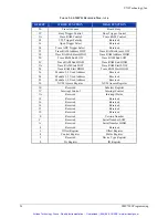
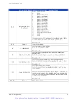
Interrupt Control Register - Read and Write
D15
Scan Function done mask
bit
0 = enabled
1 = disabled
D14
Openbus Active Event
true mask bit
0 = enabled
1 = disabled
D13-D8
Module 0-5 Busy
complete
0 = enabled
1 = disabled
D13 = Module 5,… and D8 = Module 0.
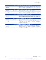
D7 IR
ENA*
0 = writing a 0 to this bit enables interrupter capabilities
1 = writing a 1 to this bit disables interrupter capabilities
D6 IH
ENA*
The module has no interrupt handler capability, therefore writing a 1
or 0 has no effect. A 1 is always read back for this bit.
D5-D3
Interrupter IRQ Line
The complement of the value programmed into these three bits
reflects the selected IRQ line used by the module. A value of 011
2
would select IRQ4, a value of 000
2
would select IRQ7, and a value
of 111
2
would disconnect the IRQ lines.
D2-D0
Handler IRQ Line
The module has no interrupt handler capability; therefore writing to
these bits has no effect. A 111
2
is always read back for these bits.
Note that all bits in this register are set to 1s upon receipt of a hard or soft reset.
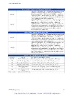
Subclass Register - Read Only
D15
VXIbus Extended Device
Always reads as 1.
D14-D0
Extended Memory Device
Always reads as 7FFD
16
NVM Access Register - Read
D15-D1
Unused
All Bits are always 1.
D0
Reads back the serial data stream from the selected SMIP
II
board.
Note that only one SMIP
II
board may be read back at a time.
NVM Access Register - Write
D15-D7
Unused
Data written to these bits have no effect.
D6
Serial clock for module 5; should be a logic 1 when not used.
D5
Serial clock for module 4; should be a logic 1 when not used.
D4
Serial clock for module 3; should be a logic 1 when not used.
D3
Serial clock for module 2; should be a logic 1 when not used.
D2
Serial clock for module 1; should be a logic 1 when not used.
D1
Serial clock for module 0; should be a logic 1 when not used.
D0
Serial data input for all modules; must be a logic 1 when not used.
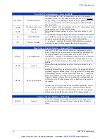
Board X, Y Used Address Register - Read and Write
D15-D8
Sets the actual number of words of address space used by the relays
on board's X.
D7-D0
Sets the actual number of words of address space used by the relays
on board's Y.
Trace RAM Start High Register - Read and Write
D15-D4
Unused
Data written to these bits have no effect and always read back as 1s.
D3-D0
Sets the four most significant bits of the starting address of the Trace
RAM, allowing the available RAM to be divided into multiple traces.
Artisan Technology Group - Quality Instrumentation ... Guaranteed | (888) 88-SOURCE | www.artisantg.com


