www.vtiinstruments.com
SMP7500 Programming
49
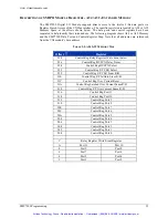
Setup PORT 0
Set PORT 0’s PORT Inn/Out Select Bit to 1; sets PORT 0 as an output port.
PORT 0 Control Register = h0001
Set PORT 0’s PORT Register Out Select Bit to 0; sets PORT 0 as immediate.
Set PORT 0’s PORT Polarity Select Bit 0; sets PORT 0’s output to non-inverted.
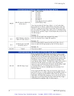
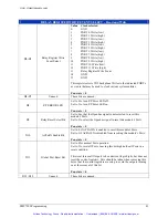
Set PORT 0’s PORT Output Clock Select Bits to 2; selects the Relay Register write Event.
PORT 0 Control Register = h0081
Set PORT 0’s PORT Output Clock Polarity Select Bit to 0; sets the polarity to non-inverted.
Set PORT 0’s PORT Output Clock Enable Bit to 1; enables the Output Clock.
PORT 0 Control Register = h0281
To achieve the state of the Port as described above, the following must be written to PORT 0’s
Control Register.
Write = h0281 to the PORT 0’s Control Register
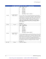
Setup PORT 2
Set PORT 2’s PORT Inn/Out Select Bit to 0; set PORT 2 as an input port.
PORT 2 Control Register = h0000
Set PORT 2’s PORT Clock to Input Port Select Bits to 0; selects the F/P CLK 2.
Set PORT 2’s PORT Clock to Input Port Polarity Bit to 0; sets polarity to non-inverted.
Set PORT 2’s PORT Input Clock Select to 1; sets to synchronous port operation.
PORT 2 Control Register = h2000
To achieve the state of the Port as described above, the following must be written to a PORT 2’s
Control Register.
Write = h2000 to the PORT 2’s Control Register
This concludes the programming of the bits that are necessary to configure PORT 0 as an output
port with it’s Output Clock driven by the Relay Register Write Event. And PORT 2 as in input
port that has it’s F/P CLK configured as an input.
The test setup is now complete. PORT 0 is ready to transmit data, and PORT 2 is ready to receive
that data.
Artisan Technology Group - Quality Instrumentation ... Guaranteed | (888) 88-SOURCE | www.artisantg.com

