www.vtiinstruments.com
SMP7500 Programming
43
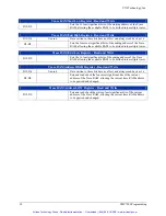
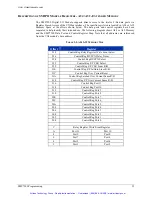
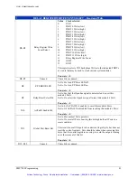
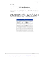
RELAY REGISTER WRITE EVENT SELECT – Read and Write
D0-D3
Relay Register Write
Event Select
Value
Clock selected
0 GND
1
PORT 0 Write (low)
2
PORT 1 Write (high)
3
PORT 2 Write (low)
4
PORT 3 Write (high)
5
PORT 4 Write (low)
6
PORT 5 Write (high)
7
PORT 6 Write (low)
8
PORT 7 Write (high)
9
PORT 8 Write (low)
10
PORT 9 Write (high)
11
PORT 10 Write (low)
12
PORT 11 Write (high)
13
Relay Register Write Event
14 GND
15 GND
This register selects VXI back plane Writes to the indicated PORTs
as events that may be used to clock various system entities.
Pon state = 0
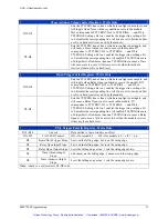
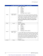
D4-D7
Unused
These bits are unused.
D8
F/P ERROR LED
Set to 0 to turn F/P Error LED off.
Set to 1 to turn F/P Error LED on.
Pon state = 0
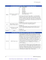
D9
Relay Reset Select Bit
Set to 0 so that the Openbus signal is not selected to reset this
module's Ports.
Set to 1 to select the Openbus signal to reset this module's Ports.
Pon state = 0
D10
ACFailN Enable Bit
Set to 0 if ACFAILN is enabled to reset this module's Ports.
Set to 1 if ACFAILN is disabled from resetting this module's Ports.
Pon state = 0
D11
Global Port Reset Bit
Set to 0 for normal Port operation.
Set to 1 to reset all Ports. Leaving this bit high holds all Ports in a
reset condition.
This reset forces all Outputs to be undriven (logic high), but does not
reset the control registers. Care should be taken when removing this
bit so that the control registers are setup to avoid the outputs turning
on at the removal of this bit.
Pon state = 0
D12-D15
Unused
These bits are unused.
Artisan Technology Group - Quality Instrumentation ... Guaranteed | (888) 88-SOURCE | www.artisantg.com


