VXI Technology, Inc.
46
SMP7500 Programming
E
XAMPLE OF A
P
ORT
S
ET AS AN
I
NPUT
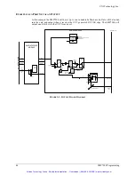
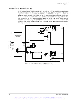
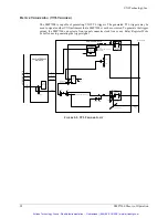
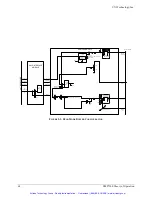
In this example the SMP7500 will be configured to clock the UUT and read 8 bits of data when a
Relay Register Write Event has occurred. It is assumed that the UUT will output data on the rising
edge of the clock that is generated by the SMP7500. The SMP7500 will capture or read data on
the falling edge of this same clock. When the SMP7500 detects that a Relay Register Write Event
has occurred, the front panel clock lines to the UUT are activated. The rising edge of the clock is
sent to the UUT. The UUT transmits data on this edge, and the data will be latched into the
SMP7500 on the falling edge. The SMP7500 module then initiates an event on a selected TTL
Trigger line that may be used to inform the slot 0 controller that the transfer has occurred, and that
data may be read back.
USER CONNECTOR
GND_I/O
(Left Floating)
DATA
GND_CLK
GLOBAL
CLK
47k
User Selectable
HW Jumpers
22
Off To All Other Ports
47K
User Selectable
HW Jumpers
120
100pf
2
2
Enable
(set)
200K
33K
R/B
Control
Writes to
Specific Port
Addresses
Control
Control
Relay Req. 000Ch Write Event
WR EVENT
R/B
I/O Data
Buffer
Data
Backplane Load
Transparent
Relay Req. 000Ch Write Event
Control
SMIP INTERFACE
MODULE
DATA
ADDRESS
CONTROL
BUSYN
TTL
TRIGGER
BUS
0-7
DATA
ADDRESS
CONTROL
VX
I
BA
C
KP
L
A
N
E
SMP7500 MODULE
Control
Trace
Memory
Polarity
Polarity
F
IGURE
3-3:
R
EAD
M
ODE
U
SING
TTL
T
RIGGER
I
N
Artisan Technology Group - Quality Instrumentation ... Guaranteed | (888) 88-SOURCE | www.artisantg.com

