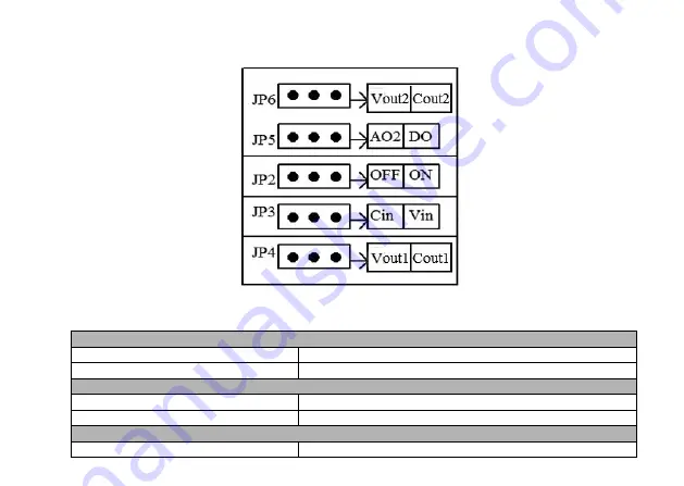
VTS Medical Systems VTS5000 Series Operating Instructions Manual Download Page 20


16 

2.10    Dial Switch 


JP6 
Vout2 

AO2 output voltage signal   

Cout2 

AO2 output current signal 

JP5 
AO2 

AO2 of AO2/DO is effective, output voltage signal 

DO 

DO of AO2/DO is effective, output pulse signal 

JP2 
OFF 

Non-connecting for matched resistance of 485 communication 

Summary of Contents for VTS5000 Series

Page 1: ...VTS5000 Series High performance Vector Inverter Operating Instruction Manual Control and protect your motor...

Page 2: ...on Environment 9 2 2 Installing Direction and Space 10 2 3 Appearance and Dimension of Keypad 10 2 4 Whole Structure 11 2 5 Basic Running Wiring 12 2 6 Major Loop Terminal Wiring 13 2 7 Major Loop Ter...

Page 3: ...word Setting and Function Code Edit 27 4 Function Parameter Table and Description 30 4 0 Monitoring Parameter Group and Fault Record 30 4 1 Function Code 35 4 2 Detailed Function Description 84 5 Comm...

Page 4: ...l Information 183 5 9 Communication Address of all Parameters 184 6 Troubleshooting 186 6 1 Fault information and Troubleshooting 186 6 2 Abnormal Phenomena Solution 191 7 Maintenance 194 7 1 Routine...

Page 5: ...nt off Any internal operation must be after making sure of discharge off with instrument checking to avoid the electric shock Do not connect AC power to output terminal U V W of inverter The only term...

Page 6: ...2 1 2 Nameplate Introduction 1 2 1 Denomination rules 1 2 2 Nameplate VTS MODEL VTS5000 2R2G 4 POWER 2 2 KW INPUT 3PH AC380V 50HZ OUTPUT 5 0A 0 300HZ 3PH 0 460V...

Page 7: ...1 5 2 2 5 0 2 2 4 0 9 0 4 0 5 5 13 5 5 7 5 17 7 5 11 25 11 15 30 15 18 5 37 18 5 1 4 Technical Index and Specification Input Rated Voltage Frequency 3 phase 4 sereis 380V 50 60HZ 1 phase S2 series 220...

Page 8: ...que low decreasing torque 1 low decreasing torque 2 square torque Torque Compensation Manual setting 0 0 30 of rated output Automatic compensation according to output current and motor parameter Autom...

Page 9: ...ery after power cut PID Control RS485 Communication Built in PID controller able to preset frequency Standard configuration RS485 communication function multiple communication protocol for choice sync...

Page 10: ...Noise Running Carrier frequency 1 0kHz 16 0kHz continuous adjustable minimize motor noise Speed Tracking and Restart Function Smooth restart during operation instantaneous stop and restart Counter A b...

Page 11: ...ge undervoltage module fault electric thermal relay overheat short circuit default phase of input and output motor parameter adjustment abnormality internal memory fault etc Environment Ambient Temper...

Page 12: ...ke terminal is connected Injury risk wiring responsibility should be beard by users 5 Do not touch output terminals directly The output terminal is connected directly to motor There should be no short...

Page 13: ...1 Operation Environment No corrosive gases vapors dust or oily dust no direct sunlight No floating dust and metal particle Ambient humidity 20 90 RH Vibration less than 5 9m s2 0 6g No electromagnetic...

Page 14: ...10 2 2 Installing Direction and Space To ensure a good cooling cycle the VFD must be installed vertically and keep enough space from surroundings 2 3 Appearance and Dimension of Keypad...

Page 15: ...7G 4 0 75 106 174 5 160 167 118 184 5 3 5 1 95 VTS5000 1R5G 4 1 5 VTS5000 2R2G 4 2 2 VTS5000 004G 4 4 0 148 5 236 177 184 160 247 6 0 4 6 VTS5000 5R5G 4 5 5 VTS5000 7R5G 4 7 5 VTS5000 011G 4 11 206 30...

Page 16: ...ring The wiring parts of VFD include major loop and control loop Open the cover of I O terminals users can see the major loop terminal and control loop terminal and must conduct the wiring according t...

Page 17: ...13 2 6 Major Loop Terminal Wiring 2 7 Major Loop Terminal Diagram 2 8 Control Loop Terminal Diagram...

Page 18: ...cuit output channel 2 can be programmed as DO terminal of various functions common port COM OUTPUT maximum load current 50mA Y2 DO Can be programmed as impulse output terminal of various functions as...

Page 19: ...rcuits of all digital signal input terminals Maximum output current 200mA Control terminal AI1 can input both voltage and current signal while AI2 can only input voltage signal users can conduct corre...

Page 20: ...AO2 output voltage signal Cout2 AO2 output current signal JP5 AO2 AO2 of AO2 DO is effective output voltage signal DO DO of AO2 DO is effective output pulse signal JP2 OFF Non connecting for matched r...

Page 21: ...wired separately with shielding and away from major loop wiring When carrier frequency is less than 4kHz keep the distance between VFD and motor within 50m when carrier frequency exceeds 4kHz make an...

Page 22: ...during VFD failure or tripping Adding spare circuit is recommended under this circumstance to ensure safety Note confirm and test the operation characteristic of the spare circuit in advance to ensur...

Page 23: ...s Key Name Function Description Programmin g escape key Enter or escape from programming Shift monito r key Choose the bit of the data which is to be set and modified when the VFD is in edit status sw...

Page 24: ...key if run command channel is set as keyboard stop effective mode The VFD will be reset and resume normal stop status after pressing this key when the VFD is in malfunction status Analog potentiomet e...

Page 25: ...D is in reverse running status REMOTE Remote control indicator Table 1 3 Unit Indicator Light Description LED Indicator A Current displayed parameter is current with unit of A LED indicator light A is...

Page 26: ...lt setting in sequence is main setting frequency bus voltage Other monitoring parameters can be set to display by function code FE 10 FE 11 for details see function code table FE 10 FE 11 or without p...

Page 27: ...play The VFD enters into malfunction alarm display status upon detecting failure signal and display failure code as shown in Fig 3 4 Press to check relative parameters of stopped inveter to check fail...

Page 28: ...erter 3 6 Function Code Editing Display Under stop run or fault alarm status press key to enter editing status which is displayed as two classes menu input the password first if it is preset see passw...

Page 29: ...D 00 and the indicator light of unit Hz is on Example 2 check monitoring parameter item d 05 output current Method 1 Press key to enter programming status LED displays function code F0 00 press again...

Page 30: ...s and latest 3 times 3 8 Function Code Setting The function parameter system of this inverter includes function code F0 FF fault code E group and monitoring code D group Each function group is consist...

Page 31: ...parameter set here is only not restricted by password protection but is restricted by conditions like whether is revisable during running the monitoring parameters etc When setting the user password...

Page 32: ...place tens place and ones place of function items Press key or key to modify the digit in the according digit place LED displays F1 20 Press the according data of F1 20 is displayed Press to enter F1...

Page 33: ...29 00000 F0 00 F1 03 22222 En F0 01 F0 00 00000 55555 F0 01 F1 02 0 0 Escape 50 0 0 F0 0 0 1s F1 02...

Page 34: ...2 Estimated Motor Frequency 0 00 maximum output frequency F0 15 Note motor running frequency converted from estimated motor speed 0 01Hz 0 00 d 03 Main Set Frequency 0 00 maximum output frequency F0 1...

Page 35: ...A 0 01V 0 00 d 17 Analog Input AI2 V 0 00 10 00V 0 01V 0 00 d 18 Impulse Frequency Imput KHz 0 00 50 00KHz 0 01KHz 0 00 d 19 Analog Output AO1 V mA 0 00 10 00V mA 0 01V 0 00 d 20 Analog Output AO2 V 0...

Page 36: ...overcurrent limit BIT10 overvoltage limit BIT11 amplitude limiting of torque BIT12 amplitude limiting of speed BIT13 speed control BIT14 torque control BIT15 reserved 1 0 d 24 Current stage of multist...

Page 37: ...r 0 65535H 1H 0 d 36 accumulative power on time of VFD hour 0 65535H 1H 0 d 37 accumulative run time of fan hour 0 65535H 1H 0 d 38 Accumulative electricity consumption low order digit 0 9999KWH 1KWH...

Page 38: ...ved 0 d 45 Special model monitoring parameter reserved 0 d 46 Special model monitoring parameter reserved 0 d 47 Special model monitoring parameter reserved 0 d 48 The third to last fault type 0 30 1...

Page 39: ...5 X4 X3 X2 X1 1 0 d 56 Output terminal status of current fault 0 FH Note sequence from high to low order digit in binary system R1 Y2 Y1 1 0 d 57 Run state of current fault 0 FFFFH 1 0 4 1 Function Co...

Page 40: ...W Depending on model F 0 04 VFD type 0 G type constant torque load type 1 P type fan water pump load type Note 1 set as P type and the VFD parameters will refresh automatically without modifying any p...

Page 41: ...inal run command channel 2 communication run command channel 1 0 o F 0 07 Main frequency source A 0 digital set 1 keypad key encoder F0 12 1 digital set 2 terminal UP DOWN adjust F0 13 2 digital set 3...

Page 42: ...A K B 6 switch from A to K B A prior to K B 7 switch form A to A K B A prior to A K B 8 switch form A to A K B A prior to A K B 9 Panel potentiometer Note 1 frequency switch needs Note 2 compared wit...

Page 43: ...ght coefficient K setting 0 01 10 00 0 01 1 00 o F 0 15 Maximum output frequency Low frequency range MAX 50 00 F0 16 300 00 High frequency range MAX 50 00 F0 16 3000 0 0 01Hz 50 00 F 0 16 Upper limit...

Page 44: ...l o F1 Group Auxiliary Operating Parameters F 1 00 Start mode 0 start at start frequency 1 DC braking start at start frequency 2 start with speed tracking 1 0 F 1 01 Start frequency 0 00 50 00Hz 0 01H...

Page 45: ...3 Acc time 2 0 1 3600 0s 0 4 4 0KW 7 5s 5 5 30 0KW 15 0s 37 0 132 0KW 40 0s 160 0 630 0KW 60 0s 0 1 Depending on model o F 1 14 Dec time 2 0 1 Depending on model o F 1 15 Acc tinme 3 0 1 Depending on...

Page 46: ...per limit freq 0 01Hz 0 00 o F 1 29 Hopping freq 3 0 00 upper limit freq 0 01Hz 0 00 o F 1 30 Hopping fre 3 range 0 00 upper limit freq 0 01Hz 0 00 o F 1 31 Action when set freq is lower than lower li...

Page 47: ...er can not be initialized please modify it manually 1 0 F 2 01 Motor s rated power 0 4 999 9KW 0 1KW Depending on model F 2 02 Motor s rated freq 0 01Hz F0 15 maximum freq 0 01Hz 50 00 F 2 03 Motor s...

Page 48: ...action 1 static tuning 2 no load complete tuning 3 on load complete tuning 1 0 F 2 17 Pre excitation time of asynchronous motor 0 00 10 00s 0 4 4 0KW 0 02s 5 5 30KW 0 05s 37 132KW 0 10s 160 630KW 0 20...

Page 49: ...Vector control of positive slip compensation factor electromotion state 50 0 200 0 rated slip frequency 0 1 100 0 o F 4 09 Vector control of negative slip compensation factor braking state 50 0 200 0...

Page 50: ...torque limit of vector mode G type 0 0 200 0 rated current of motor 180 0 P type 0 0 200 0 rated current of motor 120 0 0 1 Depending on model o F 4 21 Braking torque limit of vector mode G type 0 0...

Page 51: ...el F 4 24 Torque detection time 0 0 10 0s 0 1s 0 0 F 4 25 Cut off freq of static friction coefficient 0 00 300 00Hz 0 01Hz 10 00 o F 4 26 Static friction coefficient set 0 0 200 0 0 1 0 0 o F 4 27 Hol...

Page 52: ...e of motor F2 04 0 1 Depending on model F 5 08 Torque boost cutoff point 0 00 rated freq of motor 0 01Hz 15 00 F 5 09 V F control slip frequency compensation 0 0 200 0 rated slip note default as 100 0...

Page 53: ...0 digital setting 1 AI1 2 AI2 1 0 o F5 14 voltage feedback method of voltage close loop output 0 AI1 1 AI2 Note only valid for closed loop output mode 1 0 F5 15 Output voltage of digital setting 0 0 2...

Page 54: ...imiting value 2 protection action and free stop 1 0 F5 22 Detection value of voltage feedback disconnection 0 0 100 0 rated voltage of motor 0 1 2 0 o F5 23 Detection time of voltage feedback disconne...

Page 55: ...A 10 00V 20 00mA 0 01V 10 00 o F6 04 AI1 upper limit corresponding physical quantity setting 200 0 200 0 Note range is relevant to F6 00 0 1 100 0 o F6 05 AI1 input smoothing time 0 00S 10 00S 0 01S 0...

Page 56: ...of zero freq operation Zero freq hysteresis 50 00Hz 0 01Hz 0 00 o F6 14 zero freq hysteresis 0 00 zero freq threshold value 0 01Hz 0 00 o F6 15 External impulse input corresponding physical quantity...

Page 57: ...fore slip compensation 1 output frequency after slip compensation 2 set frequency 3 motor speed estimated value 4 output current 5 output voltage 6 but voltage 7 PID specified value 8 PID feedback val...

Page 58: ...00 10 00V 0 01V 0 00 o F6 30 Physical quantity correspond to AO2 output upper limit 200 0 200 0 0 1 100 0 o F6 31 AO2 output upper limit 0 00 10 00V 0 01V 10 00 o F6 32 Physical quantity correspond to...

Page 59: ...sponds setting 200 0 200 0 Note range is relevant to F6 00 0 1 0 0 o F6 39 AI1 Curve turning point1 input F6 37 F6 41 0 01V 3 00 o F6 40 AI1 Curve turning point1 input corresponds setting 200 0 200 0...

Page 60: ...45 F6 49 0 01V 3 00 o F6 48 AI2 Curve turning point1 input corresponds setting 200 0 200 0 Note range is relevant to F6 06 0 1 30 0 o F6 49 AI2 Curve turning point2 input F6 47 F6 51 0 01V 6 00 o F6 5...

Page 61: ...d 3 18 multi speed 4 19 ACC DEC time TT1 20 ACC DEC time TT2 21 run command channel 1 22 run command channel 2 23 VFD ACC DEC prohibit 24 VFD operation prohibiting 25 run command switch to keypad 26 r...

Page 62: ...e status reset 38 PLC control input 39 PLC pause 40 PLC reset 41 clear the counter to zero 42 input signal to trigger the counter 43 timing triggering input 44 timing clearing input 45 input external...

Page 63: ...setting of input terminal X1 X7 0 7FH 0 is positive logic i e terminal Xi is enabled when it connects with common terminal and disabled if disconnected 1 is negative logic i e terminal Xi is disabled...

Page 64: ...tion signal FDT2 6 freq speed arrival signal FAR 7 VFD zero speed running 8 upper limit arrival of output freq 9 lower limit arrival of output freq 10 lower limt arrival of preset freq during running...

Page 65: ...d write failure encoder disconnection etc 23 AI1 AI2 24 preset length arrival 25 preset operation time out 26 dynamic braking action 27 DC braking action 28 flux braking action 29 torque limiting 30 o...

Page 66: ...z F0 16 upper limit freq 0 01Hz 50 00 o F7 26 FDT1 lag 0 0 100 0 F7 25 0 1 2 0 o F7 27 FDT2 detection method 0 speed set value 1 speed detected value 1 0 o F7 28 FDT2 level 0 00Hz F0 16 upper limit fr...

Page 67: ...g 0 65535S 1s 0 o F7 37 Y1 turn off delay time 0 0 100 0s 0 1s 0 0 F7 38 Y2 turn off delay time 0 0 100 0s 0 1s 0 0 F7 39 R1 turn off delay time 0 0 100 0s 0 1s 0 0 F7 40 R2 turn off delay time 0 0 10...

Page 68: ...positive 1 negative LED ten s place proportion regulation reserved 0 integral regulation of constant proportion 1 integral regulation of auto changing proportion LED hundred s place integral regulati...

Page 69: ...ding or lower than sleep threshold 2 sleep when feedback pressure and output frequency are stable 1 1 F8 13 Stop method of sleep mode 0 decelerate to stop 1 coast to stop 1 00 0 o F8 14 Deviation limi...

Page 70: ...F8 24 not supported by hardware 0 disabled 1 PFC enabled 2 SPFC enabled 1 0 F8 22 Delay time of terminal disconnect and connect 0 0 6000 0s 0 1s 0 1 o F8 23 Polling time 0 0 6000 0s 0 1h 48 0 o F8 24...

Page 71: ...mit frequency 0 01Hz 0 00 F9 Group MS and PLC Running Traverse and Fixed Length Control F9 00 PLC running mode 0 stop after single cycle 1 retain value after single cycle 2 continuous cycle of limited...

Page 72: ...ncy 7 upper limit Freq upper limit Freq 0 01Hz 50 00 o F9 14 MS frequency 8 upper limit Freq upper limit Freq 0 01Hz 0 00 o F9 15 MS frequency 9 upper limit Freq upper limit Freq 0 01Hz 0 00 o F9 16 M...

Page 73: ...F9 33 Run time of stage 5 0 0 65535 5 S M 0 1S M 0 0 o F9 34 Acc Dec time of stage 6 0 3 1 0 o F9 35 Run time of stage 6 0 0 65535 5 S M 0 1S M 0 0 o F9 36 Acc Dec time of stage 7 0 3 1 0 o F9 37 Run...

Page 74: ...13 0 3 1 0 o F9 49 Run time of stage 13 0 0 65535 5 S M 0 1S M 0 0 o F9 50 Acc Dec time of stage 14 0 3 1 0 o F9 51 Run time of stage 14 0 0 65535 5 S M 0 1S M 0 0 o F9 52 Acc Dec time of stage 15 0 3...

Page 75: ...s 0 1s 0 0 F9 62 Traverse amplitude 0 0 100 0 0 1 0 0 o F9 63 Step freq 0 0 50 0 of amplitude 0 1 0 0 o F9 64 Traverse rising time 0 1 3600 0s 0 1s 5 0 o F9 65 Traverse falling time 0 1 3600 0s 0 1s 5...

Page 76: ...0V 200V 380V 330 480V 350V 1V Depending on model FA 04 Overvoltage limit level 220V 350 390V 370V 380V 600 780V 660V 1V Depending on model FA 05 Voltage limit factor in decelerating 0 100 0 protection...

Page 77: ...model o FA 13 Overload pre alarm delay time 0 0 30 0s 0 1s 10 0 o FA 14 Temperature detection threshold 0 0 90 0 0 1 65 0 FA 15 Phase loss protection of input and output 0 disabled 1 disabled for inpu...

Page 78: ...tion according to preset mode 1 0 FA 21 Feedback disconnection detection value 0 0 100 0 0 1 0 0 o FA 22 Feedback disconnection detection time 0 0 3600 0S 0 1S 10 0 o FA 23 Reserved 0 FA 24 Action of...

Page 79: ...1 alarm and maintain the current operation 1 0 FA 29 FA 3 5 Reserved 0 FB Group RS485 Communication Parameters FB 00 Protocol 0 MODBUS 1 user defined 1 0 FB 01 Local address 0 broadcast address 1 247...

Page 80: ...d 2 only enabled when decelerating 1 1 FC 01 Initial voltage of dynamic braking 220V 340 380V 360V 380V 660 760V 680V 1V Depending on model o FC 02 Hysteresis voltage of dynamic braking 220V 10 100V 5...

Page 81: ...ng time 0 65535 h Note this parameter cannot be initialized 1 0 FC 12 Freq decreasing point of instantaneous power failure 220V 180 330V 250V 380V 300 550V 450V 1V Depending on model FC 13 Freq decrea...

Page 82: ...ten s place PWM temperature correlation 0 disabled 1 enabled LED hundred s place PWM frequency correlation 0 disabled 1 low freq adjustment high Freq adjustment 2 no adjustment for low freq high freq...

Page 83: ...lation suppressing mode2 3 Oscillation suppressing mode3 FC 20 Oscillation suppressing initial freq 0 00 300 00Hz 0 01 Depending on model o FC 21 Flux braking 0 100 0 disabled 1 0 o FC 22 Energy savin...

Page 84: ...6 Oscillation suppression upper limit freq 0 00 300 00Hz 0 01 50 00 o FC 27 Oscillation suppression coefficient 1 500 1 50 o FC 28 Oscillation suppression voltage 0 0 25 0 motor rated voltage 0 1 5 0...

Page 85: ...stop 0 disabled 1 coast to stop 1 1 o FE 04 Close loop display factor 0 01 100 00 0 01 1 00 o FE 05 Display factor of load rotating speed 0 01 100 00 0 01 1 00 o FE 06 Line speed factor 0 01 100 00 0...

Page 86: ...s place monitoring parameters display mode 0 only display main monitoring parameters 1 alternate display of main and auxiliary parameters interval time 1S LED hundred s place frequency adjustment dis...

Page 87: ...5 Parameter copy function 0 disabled 1 parameters upload to operation panel 2 all function code parameters download to the driver 3 download all function code parameters except motor parameters to the...

Page 88: ...refully and seek help from the manufacture once lost the password F0 01 Control software version 1 00 99 99 1 01 F0 02 Keypad software version 1 00 99 99 1 00 F0 03 VFD rated power 0 4 999 9KW G P Dep...

Page 89: ...ividually not according a constant V F relation It can be used in areas like variable frequency power source and EPS Note factory default is 0 for above 55KW and 1 for under 55KW F0 06 Operation comma...

Page 90: ...ey M FUNC 2 digital set 3 communication set Modify the set frequency via serial port frequency set command for details check FB group communication parameter 3 AI1 analog set 0 10V 20mA The frequency...

Page 91: ...k F0 07 description F0 09 frequency source combinational algorithm 0 9 0 0 principle frequency source A 1 A K B Principle frequency A auxiliary frequency B multiplied by weight coefficient K the sum o...

Page 92: ...is the weight coefficient of auxiliary frequency for details check F0 14 function code description F0 10 Digital freq set 1 control 000 111 000 LED units digit power down save 0 save Once power on the...

Page 93: ...eypad digital frequency F0 13 Frequency source digital setting 2 0 00Hz F0 16 upper limit 50 00 frequency When frequency channel is defined as digital given 2 principle and auxiliary frequency source...

Page 94: ...DC braking start frequency hopping frequency 4 The maximum output frequency upper limit frequency and lower limit frequency have relations as showed in figure F0 1 please notice the numerical value or...

Page 95: ...run In this mode the actual output phase sequence is opposite to the system default Key RUN and FWD terminal are both for reverse control 2 reverse run forbidden In any condition motor can only run fo...

Page 96: ...art automatically in speed tracking method F1 01 Start frequency 0 00 50 00Hz 1 00 F1 02 Start frequency hold time 0 0 10 0s 0 0 Start frequency is the initial frequency when the VFD starts as fs show...

Page 97: ...ng the accelerating start and speed reaching period and decrease start and decreasing reaching period set the speed as S curve Thus the increasing and decreasing action become smooth and the impact to...

Page 98: ...of DC brake 0 0 150 0 Ie 0 00 F0 16 upper limit freq 0 00 F1 10 DC brake delay time 0 0 150 0 Ie 0 0 100 0s 0 0 F1 11 DC brake current 0 0 150 0 rated current of motor 0 0 F1 12 DC brake time at stop...

Page 99: ...peration 0 00 F0 16 upper limit freq 5 00 F1 22 Jog Acc time 0 1 3600 0s Depending on model F1 23 Jog Dec time 0 1 3600 0s Depending on model F1 24 jog interval time 0 1 100 0s 0 1 F1 20 F1 24 defines...

Page 100: ...und some frequency point as showed in the following figure which means the VFD frequency will never stay in hopping frequency range but the the decelerating process will pass this range Fig F1 6 Hoppi...

Page 101: ...Fig F1 7 FWD REV run dead band time F1 35 FWD REV switch mode 0 1 0 0 over zero frequency switch 1 over start frequency switch F1 36 emergency stop standby deceleration time 0 1 3600 0S 1 0 F1 37 Cur...

Page 102: ...ous motor 0 1 6553 5mH Depending on model F2 09 Stator rotor mutual inductance of asynchronous motor 0 1 6553 5mH Depending on model F2 10 No load current of asynchronous motor 0 01 655 35A Depending...

Page 103: ...rameters measurement of motor Choose this mode for best when motor can be apart from load Notice 1 when set F2 16 as 2 if over current or tuning fault occurs during tuning check if there is phase loss...

Page 104: ...nnection protection 0 1 999 9rpm 0 0 F3 07 zero servo control function reserved 0 2 0 F3 08 zero servo position loop proportional gain reserved 0 000 6 000 2 000 F4 Speed Loop Torque and Flux Control...

Page 105: ...n motor slip ratio is positive and negative slip compensation factor works for the speed when motor slip ration is negative F4 10 speed and torque control selection 0 2 0 0 speed control Speed control...

Page 106: ...en using this function users should set physical quantity of AI2 input as torque command and also AI2 setting corresponding curve and AI2 input filtering time Refer to function code F6 06 F6 11 for in...

Page 107: ...req 100 0 Keypad limit speed 2 is relative to the value of maximum output frequency This function code corresponds to reverse speed limit value when F4 15 0 F4 18 Torque rise time 0 0s 10 0s 0 1 F4 19...

Page 108: ...ng and after over torque detected the VFD will stop output and the motor will coast to stop 4 output cut off after over torque detected during running Over torque is detected during the whole running...

Page 109: ...e to the power of 1 5 as curve 2 showed in Fig F5 1 3 decreasing torque curve 3 power of 1 7 Decreasing toque curve 3 output voltage value is output frequency value to the power of 1 7 as curve 3 show...

Page 110: ...low frequency torque characteristics it is feasible to boost output voltage This function code indicates automatically torque compensation with set value of 0 0 and manual torque compensation with any...

Page 111: ...djusts voltage to value of set target voltage after reaching set frequency point No feedback for voltage in this mode and the target voltage value is open loop setting Fig F5 4 Voltage Control Mode 0...

Page 112: ...T ratio 50 input AC 0 500V output DC 0 10V When output reaching the target voltage 456V the feedback voltage of PT output is 456 50V 9 12V AI1 upper limit input is 10V input voltage is 500V the ratio...

Page 113: ...ve 2 AI2 Specify target voltage value by analog quantity AI2 and the corresponding physical quantity F6 00 of AI2 should be set as 2 voltage directive F5 14 voltage feedback channel of voltage closed...

Page 114: ...ease the voltage to the amplitude limiting voltage 2 protection action and coast to stop F5 22 Detection value of voltage feedback disconnection 0 0 100 0 motor rated voltage 2 0 The maximum value of...

Page 115: ...6 AI2 input corresponding physical quantity 0 2 0 0 speed command output frequency 100 0 100 0 1 torque command output torque 200 0 200 0 AI1 analog setting value works as given value of torque comman...

Page 116: ...eration Zero frequency hysteresis 50 00Hz 0 00 When F0 18 1 high frequency mode the upper limit of this function code is 500 0Hz F6 14 Zero frequency hysteresis 0 00 zero frequency running threshold v...

Page 117: ...0 F6 20 external impulse input filtering time 0 00s 10 00s 0 05 These above function codes defined input range of impulse input channel and the corresponding physical quantity percentage Multi functio...

Page 118: ...Output current 0V 0mA AO upper limit 0 2 times of rated current 2V 4mA AO upper limit 0 2 times of rated current Output voltage 0V 0mA AO 0 1 2 times of upper limit rated output voltage 2V 4mA AO uppe...

Page 119: ...er limit 0 00 10 00V 0 00 F6 26 Corresponding physical quantity of AO1 output upper limit 200 0 200 0 100 0 F6 27 AO1 output upper limit 0 00 10 00V 10 00 F6 28 Corresponding physical quantity of AO2...

Page 120: ...0 200 0 note range is relevant to F6 00 60 0 F6 43 AI1 curve input maxmum F6 41 10 00 10 00 F6 44 AI1 curve maxmum input corresponds setting 200 0 200 0 note range is relevant to F6 00 100 0 F6 45 AI2...

Page 121: ...inal X4 function when F8 21 is non zero default as function NO 61 0 99 7 F7 04 Input terminal X5 function when F8 21 is non zero default as function NO 62 0 99 8 F7 05 Input terminal X6 function when...

Page 122: ...on brake with fastest speed This function is used in emergency stop condition The terminal is short circuited with COM and the braking will proceed with emergency standby decreasing time F1 36 11 reve...

Page 123: ...F7 1 Multi speed Running 19 Acc Dec time selection TT1 20 Acc Dec time selection TT2 By selecting the ON OFF combination of these function terminals there would be 4 kinds of acc dec time at most as...

Page 124: ...hed to keypad control from present channel forcibly If the terminal is disconnected the previous operating command channel will be enabled 26 switch operating command to terminal When this terminal fu...

Page 125: ...this function is selected Otherwise the VFD runs with preset frequency of traverse operation Refer to F9 55 F9 65 36 pause traverse operation Short circuit the terminal with COM the VFD will stop the...

Page 126: ...d in conjunction with F0 07 46 clear the length information When this function terminal is effective the information of F9 69 actual length will be cleared to get prepared for recounting See F9 67 F9...

Page 127: ...7 09 Terminal function detection when powerup 0 1 0 0 terminal control invalid when powerup During powering up even detected that the terminal of operation command is valid closed the driver will not...

Page 128: ...Xn are two random terminals among X1 X8 defined as FWD and REV function respectively In this control mode K1 is switch of run and stop K2 is for direction switching K1 K2 Xm FWD Xn REV COM Fig F7 3 2...

Page 129: ...once disconnected of the terminal the driver will runs forward F7 12 UP DOWN terminal frequency modifying rate 0 01 50 00Hz S 1 00 This function code is used to setting the frequency modifying rate of...

Page 130: ...uency reached its lower limit 10 lower limit arrival of preset frequency The signal is given if the preset frequency is lower than lower limit during VFD running 11 pre alarm signal of overload The si...

Page 131: ...When undedrvoltage of DC bus happens during stopping the LED displays PoFF when it happens during running if FA 02 0 the LED displays PoFF if FA 02 1 the LED displays E 07 and the alarm indicator is o...

Page 132: ...and this signal is sent when the corresponding segment of output terminal setting arrives 50 VFD running indication Indication signal output when VFD is in in forward reverse running state 51 temperat...

Page 133: ...ng figure Fig F7 7 Frequency Arrival F7 24 FDT1 detection mode 0 1 0 0 speed preset value 1 speed detection value F7 25 FDT1 level setting 0 00Hz F0 16 upper limit Freq 50 00 F7 26 FDT1 lag 0 0 100 0...

Page 134: ...he preset value of F7 32 the corresponding multi function output terminal will send out valid signal and the counter will be cleared to zero When the counting value reaches the preset value of F7 33 t...

Page 135: ...g setting 0 65535s 0 F7 37 Y1 turn off delay time 0 0 100 0s 0 0 F7 38 Y2 turn off delay time 0 0 100 0s 0 0 F7 39 R1 turn off delay time 0 0 100 0s 0 0 F7 40 R2 turn off delay time 0 0 100 0s 0 0 F8...

Page 136: ...r F8 02 Digital reference input 0 0 100 0 50 0 This function realized input setting of closed loop control via keypad when analog feedback is used It is only effective when digital setting of closed l...

Page 137: ...e of PID Examples are like tension control of unwinding central air conditioning control etc LED ten s place proportion regulation characteristic reserved 0 integral regulation of constant proportion...

Page 138: ...ectively but being too strong can result in repeating overshoot and cause fluctuation to system The adjustment of integral time parameter usually goes in descending order with observation of the effec...

Page 139: ...value of F8 10 and F8 11 which means operate the PID controller to increase response speed when controlled object is approaching the controlled target As showed in the following figure Fig F8 4 Closed...

Page 140: ...parameter is only valid to the first sleep mode F8 16 Threshold value of wake up 0 00 200 0 90 0 F8 15 defines the feedback value when the driver is entering sleep mode If the actual feedback is larg...

Page 141: ...PFC enabled 2 SPFC enabled F8 22 Delay time of terminal disconnect and connect 0 0 6000 0s 0 1 F8 23 Polling time 0 0 6000 0h 48 The polling time is the time to switch the frequency pump at regular i...

Page 142: ...0 01 10 00s 0 05 F8 31 Derivative time Td2 0 01 10 00s 0 00 F8 32 PID Upper limit cutoff frequency F8 33 300 00Hz 50 00 F8 33 PID Lower limit cutoff frequency 300 00Hz F8 32 0 00 Note When the freque...

Page 143: ...n the following figure Fig F9 3 PLC Continuous Cycle F9 01 Input mode of PLC running 0 1 0 0 auto 1 manual input via multi functional terminal F9 02 PLC running state saving after poweroff 0 1 0 0 not...

Page 144: ...Mode 1 2 start from the frequency where it stops fault When the driver stops caused by stop command fault or poweroff it can record both the time it has undergone in the current stage and the very fr...

Page 145: ...Multi speed freq 10 upper limit upper limit 0 00 F9 17 Multi speed freq 11 upper limit upper limit 0 00 F9 18 Multi speed freq 12 upper limit upper limit 0 00 F9 19 Multi speed freq 13 upper limit up...

Page 146: ...M 0 0 F9 40 Acc Dec time of MS stage 9 0 3 0 F9 41 Run time of MS stage 9 0 0 6553 5S M 0 0 F9 42 Acc Dec time of MS stage 10 0 3 0 F9 43 Run time of MS stage 10 0 0 6553 5S M 0 0 F9 44 Acc Dec time o...

Page 147: ...and F9 54 Reserved Reserved 0 F9 55 Traverse control 0 1 0 0 disabled 1 enabled F9 56 Input method of traverse mode 0 1 0 0 auto 1 terminal config manually When F9 56 is set at 1 if multi function ter...

Page 148: ...50 0 of traverse amplitude 0 0 This function code indicates the falling amplitude after reaching upper limit of frequency or the rising amplitude after reaching lower limit of frequency If it is set a...

Page 149: ...65 535 KM 0 000 F9 69 Actual length 0 000 65 535 KM 0 000 F9 70 Length factor 0 100 30 000 1 000 F9 71 Length calibration 0 001 1 000 1 000 F9 72 Shaft circumference 0 10 100 00CM 10 00 F9 73 Pulse pe...

Page 150: ...e speed of it which will be transmit to the drive by the sensor in the form of pulse The driver will calculate the length based on the number of pulses it received When the actual length preset length...

Page 151: ...ctor can be set to 100 as showed in Fig FA 1 Fig FA 1 Motor Overload Protection Factor When the power of VFD is larger than the motor in order to apply effective overload protection to motors with dif...

Page 152: ...model During decelerating the larger of this value the stronger of the overvoltage suppressing ability FA 06 Current limit threshold only valid in V F mode G type 80 200 VFD rated current 160 P type 8...

Page 153: ...asting time that the driver output current is lower than off load detection level FA 11 continuously after which the off load signal is sent Off load status valid means that the operating current of t...

Page 154: ...When input phase loss protection is valid and input phase loss fault occurs protection action E 12 will be enabled after a period of time defined by FA 16 and the driver will coast to stop FA 17 Dete...

Page 155: ...Loss Detection FA 23 Reserved Reserved 0 FA 24 Action of RS485 communication error 0 2 1 0 protection action and coast to stop 1 alarm and maintain current operation 2 alarm and stop according to set...

Page 156: ...n and coast to stop 1 alarm and decelerate to stop 2 alarm and keep on running FA 31 Overspeed detection value 0 0 50 0 F0 15 max freq 0 0 FA 32 Overspeed detection time 0 0 100 0s 5 0 FA 33 Action of...

Page 157: ...or RTU 2 odd parity 0 8 1 for RTU 3 no parity N 8 2 for RTU 4 even parity E 8 2 for RTU 5 odd parity 0 8 2 for RTU Notice ASCII mode is reserved at present The host should keep the same data format wi...

Page 158: ...king 220V 340 380V 360V 380V 660 760V 680V Depending on model FC 02 Hysteresis voltage of dynamic braking 220V 10 100V 5V 380V 10 100V Depending on model 10V FC 03 Action ratio of dynamic braking 10 1...

Page 159: ...t times 0 100 0 FC 07 Auto reset interval 0 1 60 0s 3 0 100 no times limit i e infinite times When fault occurs during operation the driver will stop output and display fault codes After a period of t...

Page 160: ...0 Note this parameter can be reset see description of FC 09 FC 12 Freq decreasing point of transient power failure 220V 180V 330V 250V 380V 300V 550V 450V Depending on model If the driver bus voltage...

Page 161: ...hesize method 0 seven segments of full band Current output is stable power tube of full band produces a large amount of heat 1 switch form 7 segments to five segments Current output is stable heat pro...

Page 162: ...is shorter but the current is higher other the motor decelerates smoothly with lower current but the Dec time is longer Fig FC 2 AVR Function LED ten s place overmodulation 0 disabled 1 enabled Overm...

Page 163: ...the flux braking ability and the shorter of the decelerating time Normally there is no need to set it This function is disabled if the parameter is set at 0 When overvoltage limit level is low this f...

Page 164: ...n stop status This switching is only effective to command giving method of keypad 2 clear frequency set by FE 02 Key STOP RST function 0 3 3 0 only effective to panel control Only when F0 06 0 this ke...

Page 165: ...status 0 57 5 The items of main monitoring interface can be changed by modifying the set value of the above function codes For example set PE 08 5 then output current d 05 is selected and the monitori...

Page 166: ...nction code will clear to 0 automatically FE 14 Write protect 0 2 0 0 allow all parameters to be modified some are not during operation 1 only allow F0 12 F0 13 and FE 14 to be modified 2 only allow P...

Page 167: ...04 Auxiliary Set Frequency 0 00 max output freq F0 15 0 00 d 05 Output Current 0 0 6553 5A 0 0 d 06 Output Voltage 0 999V 0 d 07 Output Torque 200 0 200 0 0 0 d 08 Motor Revolving Speed RPM min 0 3600...

Page 168: ...top BIT1 reverse forward BIT2 zero speed running BIT3 reserved BIT4 accelerating BIT5 decelerating BIT6 constant speed running BIT7 pre excitation BIT8 tuning of VFD parameter BIT9 overcurrent limit B...

Page 169: ...ime of VFD hour 0 65535H 0 d 37 Accumulative run time of fan hour 0 65535H 0 d 38 Accumulative electricity consumption low order digit 0 9999KWH 0 d 39 Accumulative electricity consumption high order...

Page 170: ...last fault type 0 30 0 d 50 Last fault type 0 30 0 d 51 Current fault type 0 30 0 d 52 Run frequency of current fault 0 00 F0 16 upper limit freq 0 00 d 53 Output current of current fault 0 0 6553 5A...

Page 171: ...xadecimal 0 9 A F Data bits 1 bit of start bit 8 bits of data send from the lower bit 1 bit of stop bit optional parity check bit refer to bit sequence of RTU data frame Error check zone cyclic redund...

Page 172: ...ODBUS digital output terminal control 0x2008 0 7FFF means 0 100 Parameter setting 0x0000 0x0F15 3 03H read multiple parameters 8 items continuously at most Inquiry information frame format send frame...

Page 173: ...d item 2 0064H read the data of F0 01 0064H read the data of F0 02 BA07H is 16 bits of CRC check code Example Name Frame format Read data of F0 01 and F0 02 Send frame 01H 03H 0001H 0002H 95CBH Return...

Page 174: ...the fault code table Send frame 01H 03H E000H 0001H B3CAH Return frame 01H 03H 02H 0013H F989H Send frame 01H 03H 1E00H 0001H 8222H Return frame 01H 03H 02H 0013H F989H Read pre alarm code A 18 addres...

Page 175: ...20H 00H Number of Data Byte 00H 01H CRC CHK High 43H CRC CHK Low CAH Analysis of this segment data if set right return the same input data Example Frame format Forward Send frame 01H 06H 2000H 0001H 4...

Page 176: ...ame 01H 06H 0800H 0001H 4A6AH MODBUS reference frequency 40HZ Send frame 01H 06H 2001H 0FA0H D642H Return frame 01H 06H 2001H 0FA0H D642H MODBUS PID reference 5V Send frame 01H 06H 2003H 01F4H 721DH R...

Page 177: ...e 01H 06H 2005H 3FFFH C3BBH MODBUS analog output AO2 output control 10V Send frame 01H 06H 2006H 7FFFH 027BH Return frame 01H 06H 2006H 7FFFH 027BH MODBUS pulse output DO output control 25KHz Send fra...

Page 178: ...f control panel 0002H amount of registers 04H bytes sum 2 register amount 0001H data of F1 00 0002H data of F1 01 2E3EH 16 bits of CRC check code Response information frame format return frame Address...

Page 179: ...000H 0002H 04H 0001H 1388H 36F8H Return frame 01H 10H 2000H 0002H 4A08H Set F1 00 at 1 Send frame 01H 10H 0100H 0001H 02H 0001H 7750H Return frame 01H 10H 0100H 0001H 0035H 6 13H read single parameter...

Page 180: ...e 13H 88H Data2 2Byte 03H 22H Data3 2Byte 00H 00H Data4 2Byte 13H 88H CRC CHK High 28H CRC CHK Low 31H Analysis of this segment data 01H address of the driver 13H write function code 000CH start addre...

Page 181: ...FCE4H Read parameter value attribute value min value of F0 12 Send frame 01H 13H 000CH 0003H 040BH Return frame 01H 13H 06H 1388H 0322H 0000H 628BH Read parameter value min value max value of F0 12 S...

Page 182: ...power off save Bit3 0 no action 1 reset Bit2 Bit1 0 no action 1 static tuning 2 dynamic tuning Bit0 0 control panel mode 1 terminal control mode 2 communication control mode 3 reserved Byte0 Bit7 VFD...

Page 183: ...code table and example of read function code 03H Read VFD fault pre alarm code E001H 1E01H Address E001H and 1E01H interchangeable refer to example of pre alarm code read function code 03H User passwo...

Page 184: ...0008H E 08 Motor overload 0009H E 09 Driver overload 000AH E 10 Driver off load 000BH E 11 Function module fault 000CH E 12 Input phase loss 000DH E 13 Output phase loss or current unbalance 000EH E 1...

Page 185: ...EH E 30 Over speed fault 5 5 Pre alarm Code of the Driver Alarm code Displayed Fault information 0000H No fault 0009H A 09 Driver overload alarm 0011H A 17 RS485 communication fault alarm 0012H A 18 K...

Page 186: ...tion 1 is output press to position 1 is shut Bit7 Bit4 Reserved Bit3 Prorammable relay output R2 Bit2 Prorammable relay output R1 Bit1 Collector open circuit output Y2 Bit0 Collector open circuit outp...

Page 187: ...10100 H 10101 KWH 10110 Bit2 Bit0 Decimal point 5 8 Error Code from Slave Response of Abnormal Information Error code Description 01H Invalid function code 02H Invalid address 03H Invalid data 04H In...

Page 188: ...d 57 D000H 1D00H D039H 1D39H Notice 1 in the above examples the driver address is 01 which makes it better for illustration when the driver is slave the address setting range is 1 247 and if any data...

Page 189: ...nterchangeable 3 Frame format when the slave response information is abnormal driver address 80H function code 16bit CRC check code if the salve return frame is 01H 83H 04H 40F3H then 01H is slave add...

Page 190: ...6 1 Fault Diagnosis and Troubleshooting Fault code Fault descriptions Possible reasons Actions E 01 Over current in Acc process Too short Acc time including tuning process Prolong the Acc time Restart...

Page 191: ...eed tracking start Special potential energy load Connect suitable braking resistor or braking unit E 05 Over voltage in Dec process Too short Dec time including tuning process Prolong the Dec time The...

Page 192: ...rve and torque boost value Low network voltage Check network voltage Too short Acc time Prolong Acc time Too heavy load Select the driver with larger power E 10 Off load Output current lower than off...

Page 193: ...ation channel E 17 RS485 communication failure Mismatching with baud rate of host PC Adjust the baud rate RS485 channel interference Check whether the communication wiring is shield whether the wiring...

Page 194: ...ion panel to the driver Check wiring of operation panel Parameter download without upload in advance Upload parameters first then download E 24 PID feedback disconnecting PID feedback wire is loosen C...

Page 195: ...keypad Measure the voltage of internal control source to check if the switching power supply is functioning well If not check its inlet wire start oscillation and stabilivolt to see if they works well...

Page 196: ...or parameters and actual values to see if they are matched meanwhile tune the motor parameters Mismaching of motor power and driver power Set the motor parameters at actual value One driver for severa...

Page 197: ...bad connect or the frequency setting signal is in fluctuation Switch to digit setting mode or increase filter time constant of analog input signal The rotation direction of motor is in reverse Adjust...

Page 198: ...ng from the driver or motor 3 high ambient temperature 4 whether the load current is as usual 5 whether the cooling fan of the driver runs normally 7 2 Periodic Maintenance To maintain a long term nor...

Page 199: ...ducts and take anti static measure 6 before performing insulation tests to the driver dismantle the wiring between the driver and the power supply the driver and motor and all main circuit input outp...

Page 200: ...STAL CODE CONTACT PERSON TELEPHONE FAX SERIAL NUMBER POWER TYPE CONTACT NO PURCHASE DATE SERVICE COMPANY CONTACT PERSON TELEPHONE TECHNICIAN TELEPHONE REPAIR DATE USER COMMENT GOOD NORMAL BAD NOTES US...

Page 201: ...Version V0119A...

Reviews: