Vonsch Quatrofrem Series Configuration And Diagnostics Download Page 171


UNIFREM v.3.41x  

10 May 2017 


Page 171 from 180 

Panel function selection 


MONITOR 

Monitor view (Monitor detail) 
 
Setpoint frequency setting, if control panel is selected as the setting 
source 


GRAPH 

Signal record displaying. 
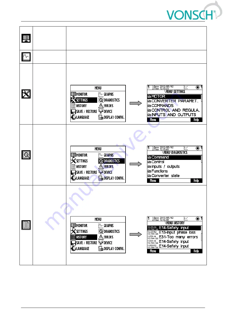
 

SETTING 

Converter parameter setting in the tree structure. Move by using selection 
arrows or by using the F1 button to the SETTINGS item and confirm by 
pressing ENTER. 


DIAGNOSTICS 

All converter status informations displaying in the tree structure.Move by 
using selection arrows or by using the F1 button to the item 
DIAGNOSTICS and confirm by pressing ENTER. 


HISTORY 

Move by using selection arrows or by using the F1 button to the item 
HISTORY and confirm by pressing ENTER. Converter events 
(Parameters restore, parameter change..) and event history displaying 
(date and time of event emergence, description). After fault or event 
selection, recorded data at emergence will be displayed. 


EXAMPLE: 

Summary of Contents for Quatrofrem Series

Page 1: ...10 May 2017 Page 1 from 180 Configuration and diagnostics for UNIFREM and QUATROFREM output side frequency converters...

Page 2: ...UNIFREM v 3 41x 10 May 2017 Page 2 from 180...

Page 3: ...Process controller 21 4 4 4 Optimization 22 4 4 5 Lifting functions 22 4 4 6 Pantograph 22 4 4 7 Ext thermal protection 23 4 4 8 Differential 23 4 5 Converter state 23 4 6 Thermal protections 24 4 7 C...

Page 4: ...RELAY OUTPUTS 80 7 6 4 ANALOG OUTPUTS 82 7 6 5 IRC1 84 7 6 6 IRC2 ARC 85 7 7 FUNCTIONS 85 7 7 1 PLC FUNCTIONS 85 7 7 2 LIMIT SWITCHES 95 7 7 3 PROCESS CONTROLLER 97 7 7 4 OPTIMIZATION 100 7 7 5 MECHAN...

Page 5: ...tion 156 8 15 Using the parameter set switching for a special behavior of converter functions 158 9 UNIFREM Frequency converter settings examples 162 9 1 Process controller PC setting to control the l...

Page 6: ...UNIFREM v 3 41x 10 May 2017 Page 6 from 180 WARNING This manual dedicates to the parameters and options of VONSCH UNIFREM frequency converter settings and diagnostics...

Page 7: ...ENU PARAMETERS ID unique identification number SETTINGS DIAGNOSTICS SAVE RESTORE Value the value number Word array of bits Constant Date time The value Calculated parameters Selection 1 option selecti...

Page 8: ...eset RESET signal of the OPS is active Detection Autodetection of the overload limits is running Overload Overload occurred Operation in the positive direction up is blocked Tipping Too many forbidden...

Page 9: ...mines the value of permanent motor current for motor overload protection P 27 Motor overloading MENU SETTINGS MOTOR Basic information about the importance of the parameter Range of the value that para...

Page 10: ...lled over the serial communication See the MODBUS serial communication protocol PROFIBUS The converter start is controlled over the serial communication See the PROFIBUS serial communication protocol...

Page 11: ...TINGS INPUTS AND OUTPUTS ANALOG OUTPUTS AO1 Selection of the signal that will linearly recalculate the analog output AO1 Parameter type COMMAND Name ID Description Def Reset the consumption 897 This c...

Page 12: ...elay R1 switches on at active bite Failure of converter status word Parameter to enter a password to allow access to the specific levels of converter setting respectively to unlock some of the modes T...

Page 13: ...rs directory choice defining EXAMPLE INPUTS AND OUTPUTS root directory selection for the transfer of parameters from set 1 to set 3 Parameter type PATH Name ID Description Def Directory The choice of...

Page 14: ...V Unifrem 230 M 220 420 Unifrem 400 400 M 425 735 Unifrem 500 350 900 Unifrem 690 730 1 250 3 2 Temperatures Warning line C Fault line C CB temperature 75 55 70 Cooler temperature 74 Unifrem 230M 400...

Page 15: ...ter fault COMPENSATION DT Turn on the dead time compensation mode SCALAR VECTOR 0 scalar control 1 vector control UNF BOARD TYPE 0 UNF 400 1 UNF 230 400 M RAMP_F_VSTUP0 Frequency ramp input reset RAMP...

Page 16: ...stic group of quantities dealing with the energy indicators power consumption losses MENU DIAGNOSTICS CONTROL POWER AND ENERGY Name ID Description Dim Input power 70 Active motor input power of the mo...

Page 17: ...according to connection V 4 2 3 Positioning Group of parameters number 1146 Quantities for position control diagnostics MENU DIAGNOSTICS CONTROL POSITIONING Name ID Description Dim Pos setpoint 1149 P...

Page 18: ...Parameters of the analog input can be configured in the parameter group 148 page 78 AIN4 282 Value of the signal brought to the analog input terminals X1 17 and X1 18 in physical units Using the param...

Page 19: ...cessary to correctly configure IRC2 pulses 827 page 85 Hz Freq IRC1 gear 1540 Speed from IRC1 sensor at gear output Hz Freq IRC2 ARC gear 1541 Speed from IRC2 ARC position sensor at gear output Hz Fre...

Page 20: ...difference at gear output in revolutions ARC ARCm IRC1 position gear 1622 ARC master ARCmaster or IRC1 position at gear output in revolutions IRC1 pos 32b high 1616 High 32 bits of IRC1 position at g...

Page 21: ...ed limit switch function km LS2 Track 892 Number of meters run during the activated limit switch function m LS2 Track in km 930 Number of kilometers run during the activated limit switch function km L...

Page 22: ...difference between two consecutive optimization algorithm samples see 65 page 100 OPT Starting point 708 Defines the starting point of the optimization at the optimization start when scanning is turne...

Page 23: ...voltage drop on the ETP sensor V Sensor resistance 871 Resistance value of the ETP sensor By multiple sensors connected to a series it represents the average resistance value on one of them 4 4 8 Diff...

Page 24: ...rloads MENU DIAGNOSTICS THERMAL PROTECTIONS Name ID Description Dim Cooler temperature 74 Temperature of the power elements cooler Converter generates a warning W6 Cooler temperature page 28 after exc...

Page 25: ...e hex Last length 665 Size in bytes of the last received frame over MODBUS Last CRC 666 Last received CRC it can also be a frame for another device hex Message count 740 Count of all received messages...

Page 26: ...rator Inactive ramp input is set to zero active normal operation of the ramp input block Unfreeze Ramp Inactive ramp output is frozen active ramp is operating normally Enable Setpoint Inactive ramp in...

Page 27: ...nd part of the converter unique serial number hex Parameter date 380 Parameter generating date Parameter time 381 Parameter generating time 4 9 Date and Time Group of parameters number 1213 MENU DIAGN...

Page 28: ...LTS window W8 DC Undervoltage Low voltage of the DC link The value Voltage DC 46 page 16 dropped under the fault limit DC Undervoltage control and evaluation of other faults is blocked For the duratio...

Page 29: ...parameter V f Identification Rs 383 page 62 is turned on motor can stay longer on zero frequency during the first start For the duration of the warning the value of Stator resistance 345 page 45 is di...

Page 30: ...icate with the converter for a defined period of time MB Warning timeout 962 page 113 F43 Limit switch 1 Limit switch 1 is switched Configuration is possible in the group 876 page 95 F44 Limit switch...

Page 31: ...lift Dynamic lift limits the maximum frequency according to the actual motor load DL can be configured in the group 1068 page 104 For the duration of the warning the value of Load 854 page 22 is disp...

Page 32: ...08 For the duration of the fault the value of Freq INV 47 page 15 is displayed in FAULTS window E11 Overcurrent Exceeding the maximal allowed output current whose value depends on the parameter Operat...

Page 33: ...s impure by conductive impurities Please contact VONSCH company For the duration of the fault the sum of phase currents is displayed in FAULTS window E31 Too many faults More faults occurred that spec...

Page 34: ...conditions for termination of trial operation E53 Identification fault Incorrect result of the motor parameters identification Please look to Manual for vector control setting For the duration of the...

Page 35: ...ne manually This quick setup wizard can only be used with the control panel UNIPANEL firmware version 2 061 or higher 7 1 1 Working with the wizard The quick setup wizard offers several type of screen...

Page 36: ...ver different command macros for different applications 5 Directions and encoder In this step the correct direction of rotation of the motor and encoder are determined 6 Control and regulation In this...

Page 37: ...s 356 Motor power factor 227 Motor overloading 27 self cooling forced cooling Sine filter SF 237 Step 3 Application macros Application macro selection Pump Fun Heavy load Compressor Conveyor travel Li...

Page 38: ...ump Fan Compressor Heavy Load Conveyor travel Lift 23 Operation mode Variable load Variable load Constant load Constant load Constant load Constant load 24 Permanent current Service settings Service s...

Page 39: ...No change No change No change No change 220 Value 0 No change 8 Hz No change No change No change No change No change 239 Value 1 No change 15 Hz No change No change No change No change No change 245 V...

Page 40: ...peed and encoder speed Was the polarity ok Encoder polarity is correct Encoder polarity was inverse This has been fixed YES NO Finished ok YES Phase order has been changed by software Test of proper r...

Page 41: ...want to perform an identification of motor parameters which rotates the motor Ident Lm short 1498 Identification successful Mag curve identification failed Please follow the documentation Mag curve id...

Page 42: ...RT command after 5 20 seconds the motor accelerates to 25Hz in the desired direction then it stops automatically The START command must be entered manually according to the actual settings This identi...

Page 43: ...rs of the 400V 55kW motor Motor 400 75 686 Parameters of the 400V 75kW motor Motor 400 90 687 Parameters of the 400V 90kW motor Motor 400 100 688 Parameters of the 400V 100kW motor Motor 400 110 689 P...

Page 44: ...time the motor when it is allowed to set the wye voltage for a delta connection while increasing the values of nom frequency and nom revolutions to 173 of their original values Nom frequency 4 Nomina...

Page 45: ...revious PWM turning off Magnetizing current 355 Magnetizing current of the motor I0 This parameter has no meaning for SMPM 2 00 A 0 01 INK2 4 Correct value of the magnetizing current is generally 30 t...

Page 46: ...t under different values of stator current MAG CURVE Group of parameters number 1158 Settings of the magnetization curve points MENU SETTINGS MOTOR SPECIAL PARAMETERS OF THE MOTOR MAG CURVE Name ID De...

Page 47: ...frequency Nom slip freq 1050 Nominal electric slip frequency calculated from the motor nameplate parameters Hz 7 3 CONVERTER PARAMETERS Group of parameters number 197 Operating parameters of the conve...

Page 48: ...assword needs to be entered when entering the converter settings Protects the converter settings against reconfiguration by unauthorized persons DST Time shift 770 Determines whether the time of the c...

Page 49: ...er the activation of the 1st or 4th binary input MODBUS The converter start is controlled over the serial communication See the MODBUS serial communication protocol PROFIBUS The converter start is con...

Page 50: ...vation the Start when selected signal is of numeric type value Look choises of parameter s Binary inputs 184 page 17 SPECIAL RESET Group of parameters number 333 Special RESET setting MENU SETTINGS CO...

Page 51: ...the setpoint are arrow keys in the MONITOR window in the control panel AIN1 The source of the setpoint is the corresponding analog input AIN2 The source of the setpoint is the corresponding analog inp...

Page 52: ...eq setpoint During power off During power off The converter keeps the setpoint value after the power off During set change Setpoint value is transferred between the parameter sets SPECIAL SETTING Grou...

Page 53: ...value 256 AIN1 Signal Torque reverse signal 654 Selection of the signal for Torque Reverse control Signal Torque reverse active 655 The condition for activation of Torque Reverse Torque reverse inact...

Page 54: ...Physical dimension and range of values are inherited according to the target where the signal is connected Warning When configuring speed control of a crane drive it might be necessary to set Value 0...

Page 55: ...ary switch special setting MENU SETTINGS COMMANDS DISCRETE SETPOINTS DS SWITCH SPECIAL SETTING DS Name ID Description Def Bit1 DS mask 553 Binary switch bit will be active if at least one of the selec...

Page 56: ...or the down command None Look choises of parameter s Quick stop source 986 page 49 SPECIAL SETTING Group of parameters number 138 Special source setting for up and down commands MENU SETTINGS COMMANDS...

Page 57: ...ensation High stability and robustness of the control Suitable for pumps fans conveyors and low momentum applications V f closed V f control scalar with the speed feedback from the motor rotation spee...

Page 58: ...V f control method operation IR compensation Turns on the stator resistance loss compensation 973 page 59 Requires correct value of the motor parameters and the stator resistance Stator resistance 34...

Page 59: ...erated permanently in STC range unless is cooled sufficiently MENU SETTINGS CONTROL AND REGULATION V F CONTROL V F CURVE ST CONTROLLER STC Name ID Description Def STC Mode 1590 Additional STC features...

Page 60: ...the unstable part of the torque speed curve of the motor If the slip compensation is turned on the desired frequency will be generated so it will not differ from the rotor frequency Freq RT 937 page...

Page 61: ...00 s Determines the current regulation dynamics using the MCC When changing this parameter we always recoomend consulting this step with the VONSCH s r o service D term of the MCC 1047 Gain value of t...

Page 62: ...very start and satisfying the conditions of measurement low speed the resistance is identified and written to parameter Stator resistance 345 page 45 Turned off Stator resistance is not identified Mag...

Page 63: ...Motor can be excited to high flux levels Opt min Flux 1485 Minimum flux value during minimum losses flux optimization 40 0 1 0 100 0 SPEED CONTROLLER SC Group of parameters number 445 Speed controller...

Page 64: ...decreases MENU SETTINGS CONTROL AND REGULATION VECTOR CONTROL MAX VOLTAGE CONTROLLER MVC Name ID Description Def Field weakening 109 Turning on motor field weakening operation Turned on Turned on Oper...

Page 65: ...e tractive force is achieved Ramp up time 838 Starting time from zero to the maximal motor torque Smooth torque change can reduce the jerk during the start of the drive However long ramp times degrade...

Page 66: ...s 0 00000000 Min position setpoint 1139 Max position setpoint 1140 Pos feedback source 1141 Selecting the source of the position feedback Position 1147 page 17 IRC1 IRC1 Position feedback is evaluated...

Page 67: ...number 833 Setting the special calibration source MENU SETTINGS CONTROL AND REGULATION VECTOR CONTROL POSITIONING SPECIAL CALIBRATION Name ID Description Def Calib signal 1145 Calibration signal Eithe...

Page 68: ...ne Lm Mutual inductance was identified Online Lssigma Leakage inductance was identified Online J Inertia moment was identified Mag curve Magnetization curve was identified Identification fault 1093 Rs...

Page 69: ...ive which is superior to all other ways of entering the speed Ramp type 107 Setting the method of entering the frequency ramp parameters Time adherent Time adherent For setting the ramp speed the ramp...

Page 70: ...Hz s 30000 000 Hz s The frequency ramp deceleration in the first ramp down section Ramp down 2 slope 129 Setting the ramp down slope from frequency Max frequency 111 page 69 to the frequency Ramp down...

Page 71: ...erter output shortly exceed this limit it depends on the load inertia rate of load and the MCC dynamics 351 page 60 6 The value depends on the inverter power line See installation manual Max regen cur...

Page 72: ...d the DYNAMIC DECELERATION controller MENU SETTINGS CONTROL AND REGULATION VOLTAGE CONTROLLER VC Name ID Description Def Kinetic backup KB 748 Turning on of the kinetic backup KB controller which main...

Page 73: ...voltage controller starts 10 0 Hz 0 0 Nom frequency 4 Regenerating is less effective on low speeds This parameter defines the minimal rotor frequency under which the voltage controller is turned off 7...

Page 74: ...pter 3 1 Undervoltage overvoltage str 14 by product type 2 Refer to chapter 3 1 Undervoltage overvoltage str 14 by product type Flux braking gain 777 Setting the gain of the flux brake 1 00 0 00 100 0...

Page 75: ...r 7 6 1 BINARY INPUTS Group of parameters number 143 Binary digital inputs setting MENU SETTINGS INPUTS AND OUTPUTS BINARY INPUTS Name ID Description Def BIN HW Type 172 Binary inputs hardware evaluat...

Page 76: ...ngs need to be taken into account Direct Look choises of parameter s BIN1 Logic 716 page 75 BIN6 Filter 183 Time constant of the binary signal filter 10 ms 0 ms 30000 ms Binary input is switched on wh...

Page 77: ...input level at point B 10 00 V 0 00 V 10 00 V AIN2 Group of parameters number 149 Second analog input MENU SETTINGS INPUTS AND OUTPUTS ANALOG INPUTS AIN2 Name ID Description Def AIN2 Type 154 Analog i...

Page 78: ...TS ANALOG INPUTS AIN3 Name ID Description Def AIN3 Type 268 Analog input type 0 10 V 0 10 V Analog input level corresponds with the voltage which is measured between the terminals X1 15 and X1 16 in t...

Page 79: ...PUTS AIN4 Name ID Description Def AIN4 Type 274 Analog input type 0 10 V 0 10 V Analog input value corresponds with the voltage which is measured between the terminals X1 17 and X1 18 in the 0 to 10V...

Page 80: ...GS INPUTS AND OUTPUTS RELAY OUTPUTS RELAY 1 Name ID Description Def R1 Source 697 Relay switching function setting Motor operation Motor operation Relay will switch on when the converter is in start r...

Page 81: ...on time 316 Relay switch on time delay 0 00 s 0 00 s 3600 00 s After establishment of the switch condition the relay will switch on after a selected amount of time R2 switch off time 317 Relay switch...

Page 82: ...Group of parameters number 226 Special function setting for relay 3 R3 Source 699 page 82 must be chosen as Special Not available for the UNIFREM 400 M converter MENU SETTINGS INPUTS AND OUTPUTS RELAY...

Page 83: ...EM 400 M MENU SETTINGS INPUTS AND OUTPUTS ANALOG OUTPUTS AO2 Name ID Description Def AO2 Type 362 Analog output type Configuration possibilities are the same as in AO 1 AO1 Type 358 page 82 0 20mA Loo...

Page 84: ...r exact rotor speed and position measurement This sensor can be connected to RM UNI_IRC1 extension module Speed is displayed in the parameter Freq IRC1 434 page 19 MENU SETTINGS INPUTS AND OUTPUTS IRC...

Page 85: ...resolution and decreases the quantization noise however a high value can cause a negative effect on the speed control quality 2 1 100 IRC2 ARC direction 829 Polarity of the IRC2 ARC speed evaluation...

Page 86: ...delay 3 1035 Selecting the logical blocks which the defined on delay time On delay 3 1027 page 86 is applied to Look choises of parameter s Logical blocks 8 page 20 On delay 4 1028 LB on delay time I...

Page 87: ...on setting 1ms reaction time MENU SETTINGS FUNCTIONS PLC FUNCTIONS LOGICAL BLOCKS LB1 FAST Name ID Description Def LB1 Operation 625 Logical operation type that will be used for the logical block OR O...

Page 88: ...s LB1 Operation 625 page 87 LB2 Level 1009 Input and output type of the logical block Configuration possibilities are the same as in LB 1 LB1 Level 1008 page 87 Look choises of parameter s LB1 Level 1...

Page 89: ...level LB4 Group of parameters number 170 Fourth logical operation setting MENU SETTINGS FUNCTIONS PLC FUNCTIONS LOGICAL BLOCKS LB4 Name ID Description Def LB4 Operation 628 Logical operation type that...

Page 90: ...Signal LB5_2 switch on 605 Conditions for switching on the LB5_2 LB5_2 switch off 606 LB5_2 switch off In case of a numeric signal if the signal value is lower than the defined level LB6 Group of par...

Page 91: ...f In case of a numeric signal if the signal value is lower than the defined level LB7_2 Signal 616 Signal selection for the 2nd input of LB7 It will be processed according to the selected operation Ei...

Page 92: ...d as the sum of input signals minus NB output is calculated as the difference of input signals multiply NB output is calculated as the product of input signals minimum NB output is the minimum of inpu...

Page 93: ...peration used for the numerical block plus Look choises of parameter s NB1 operation 635 page 92 NB2 control 1280 See NB1 control 1279 page 92 Active Look choises of parameter s Bit1 DS mask 553 page...

Page 94: ...of parameters number 310 Settings of the fourth numerical block MENU SETTINGS FUNCTIONS PLC FUNCTIONS NUMERICAL BLOCKS NB4 Name ID Description Def NB4 input 1 1020 Selection of signal for the 1st inpu...

Page 95: ...LS motor will run the track LSx Track in the given direction and then stops Stop After the switch on of the LS motor stops in the given direction For reverse Limit switch responds in the reverse dire...

Page 96: ...that the converter allows to pass when activating the limit switch function set to the Track Stop type Both parameters Transmission ratio 888 page 47 and Wheel circumference 889 page 47 need to be se...

Page 97: ...t switch set to Weakening Weakening is activated for positive or negative torque according to the For reverse value 0 0 Nm Min 8 Max torque 481 8 Value depends on the parameter Source of the torque re...

Page 98: ...rolled quantity is the power Power inverted Controlled quantity is the power error is inverted Source of PC setpoint 130 Selecting the setpoint value of the process controller Value Value Parameter So...

Page 99: ...value and the PC output is at minimum If the regulation error changes so it exceeds the value Depark hyst 416 page 99 the START block will be undone and PC starts to regulate This function is used to...

Page 100: ...imization when the scanning is turned off MENU SETTINGS FUNCTIONS OPTIMIZATION START POINT OPT Name ID Description Def Start Point OPT 710 Defines the starting value of the optimization output when th...

Page 101: ...on Step mode 425 Setting the mode of optimization step calculation during the fine tuning After starting the converter and scanning the fine optimization starts slowly changes the output OPT Output 4...

Page 102: ...mmand after the START command 0 01 s 0 00 s 100 00 s From experience it is set to 0s because the brake itself and its contactor have their delays Brake reaction 520 Brake reaction time after the RELAY...

Page 103: ...erload limits for the dynamic and static mode according to the actual values of the quantity Load 854 page 22 It is necessary for the drive to operate with autodetection at a maximal allowed operation...

Page 104: ...during reviews or inspections of the technological device and should be activated with high caution Look choises of parameter s Bit1 DS mask 553 page 55 DYNAMIC LIFT DL Group of parameters number 106...

Page 105: ...the sensor resistance beyond 1000 ohm Drop under 550 ohm causes the fault to disappear KTY84 External temperature sensor is one or more KTY 84 130 KTY 84 150 KTY 84 151 sensors KTY83 85 2k External te...

Page 106: ...0 0 1 99000 0 SPECIAL SETTING ETP Group of parameters number 569 Special source setting for the ETP voltage drop measurement MENU SETTINGS FUNCTIONS EXTERNAL THERMAL PROTECTION ETP SPECIAL SETTING ET...

Page 107: ...controller of differential 0 00 1E09 1E09 Max freq diff 1241 The maximum value of the action to setpoint frequency 0 00 Hz 0 00 Hz 20 00 Hz P gain of diff 1242 Proportional gain of controller of the d...

Page 108: ...minimal value the converter generates the fault Is not evaluated Converter accepts any analog input value Overfrequency 85 Turning on the fault evaluation for exceeding the stator limit frequency Fau...

Page 109: ...zero speed period in vector control Speed step change Fault E32 IRC fault page 33 is generated during high unlike speed step change Wrong direction Warning W59 Incorrect IRC ARC direction page 31 or...

Page 110: ...SPECIAL SETTING Group of parameters number 566 Setting the special source of fault confirmation e g in the chosen time of day or over the analog input MENU SETTINGS FAULTS AND WARNINGS FAULT ACKNOWLE...

Page 111: ...warning W7 CB temperature page 28 55 0 C 20 0 Fault3 3 Refer to chapter 3 2 Temperatures str 14 by product type External warning source 560 External warning source settings If the source is active th...

Page 112: ...t will be displayed in the monitor window in the second row 46 Voltage DC Signal Monitor 3 55 Selecting the quantity that will be displayed in the monitor window in the third row 42 Current MT Signal...

Page 113: ...r generates the fault E42 Modbus Timeout page 33 when no valid request or broadcast if allowed is received from the Modbus master within the preset time Warning The converter generates the warning W42...

Page 114: ...order 0xHl 0xHh 0xLl 0xLh Word swap 32 bit data are transfered in the byte order 0xLh 0xLl 0xHh 0xHl Byte word swap 32 bit data are transfered in the byte order 0xLl 0xLh 0xHl 0xHh MB counters 1556 S...

Page 115: ...f parameter s Bit1 DS mask 553 page 55 Step 0 1514 Setting of the step It serves to determine how to recalculate 16 bit special holding register to the selected variable set by ID 0 0 8 8 For selected...

Page 116: ...urs Reset Reset Converter goes to reset Stop Converter stops Quick stop Converter stops Quick stop No action Converter will not respond to warnings PB Type 1486 Specifies the format of transmission of...

Page 117: ...erter will take its configuration Set 1 Set 1 Converter will take its configuration from 1st set of parameters Set 2 Converter will take its configuration from 2nd set of parameters Set 3 Converter wi...

Page 118: ...off 653 Bit3 switch off In case of a numeric signal if the signal value is lower than the defined level Look choises of parameter s Binary inputs 184 page 17 7 11 2 USER SETS Group of parameters numbe...

Page 119: ...m 12 1311 Signal Param 13 1312 Signal Param 14 1313 Signal Param 15 1314 Signal Param 16 1315 Signal Param 17 1316 Signal Param 18 1317 Signal Param 19 1318 Signal Param 20 1319 Signal SET 1 4 Group o...

Page 120: ...1_15 1334 N1_16 1335 N1_17 1336 N1_18 1337 N1_19 1338 N1_20 1339 SET 5 8 Group of parameters number 1293 Settings of selected parameters for sets 5 to 8 Settings of individual sets can be done by F3 k...

Page 121: ...1356 N5_18 1357 N5_19 1358 N5_20 1359 SET 9 12 Group of parameters number 1294 Settings of selected parameters for sets 9 to 12 Settings of individual sets can be done by F3 key on the control panel...

Page 122: ...1379 SET 13 16 Group of parameters number 1295 Settings of selected parameters for sets 13 to 16 Settings of individual sets can be done by F3 key on the control panel for a particular parameter MENU...

Page 123: ...parameters number 1296 Settings of selected parameters for sets 17 to 20 Settings of individual sets can be done by F3 key on the control panel for a particular parameter MENU SETTINGS PAR SETS USER S...

Page 124: ...s of selected parameters for sets 21 to 24 Settings of individual sets can be done by F3 key on the control panel for a particular parameter MENU SETTINGS PAR SETS USER SETS SET 21 24 Name ID Descript...

Page 125: ...ets 25 to 28 Settings of individual sets can be done by F3 key on the control panel for a particular parameter MENU SETTINGS PAR SETS USER SETS SET 25 28 Name ID Description Def N25_1 1440 N25_2 1441...

Page 126: ...individual sets can be done by F3 key on the control panel for a particular parameter MENU SETTINGS PAR SETS USER SETS SET 29 32 Name ID Description Def N29_1 1460 N29_2 1461 N29_3 1462 N29_4 1463 N2...

Page 127: ...UNIFREM v 3 41x 10 May 2017 Page 127 from 180...

Page 128: ...on and tuning Parameter name ID Description Nom power W 357 Usual motor nameplate parameters Nom voltage V 59 Nom frequency Hz 4 Nom current A 151 Nom revolutions ot min 356 Motor power factor 227 Out...

Page 129: ...from 180 Table Preset motor macros in frequency converters UNIFREM 400 XXX Motor power from 60W to 7 5kW Motor power from 11kW to 200kW 8 3 Motor control modes Frequency converters UNIFREM 400 can be...

Page 130: ...ep changes of the output frequency during motor control Allowed ranges of changes of frequency min max ramp break points and also times of the respective sections can be set by parameters of ramp func...

Page 131: ...itive ramp down S curve ramp up ramp curve for negative ramp up S curve ramp down ramp curve for negative ramp down S splitting zero crossing Curve rate of the S curve and its shape can be configured...

Page 132: ...ge End voltage 94 End voltage of the V f curve which corresponds the percentage value of the nominal load voltage Frequency shift Hz 98 Frequency shift of the V f curve V f Exponent 91 V f curve expon...

Page 133: ...ation mode the voltage decreases Mathematical model which is the core of IR Compensation does not reach high accuracy near zero speed thus it is necessary to adjust the frequency from which the correc...

Page 134: ...ehavior of the drive is unacceptable due to the operating conditions cranes production lines traction it is neccesary to turn off identification of RS after drive tuning 8 3 4 Starting Torque Controll...

Page 135: ...frequency setpoint Parameter ID 349 SETTINGS CONTROL AND REGULATION V f CONTROL SLIP COMPENSATION Slip compensation turned on Motor slip compensation effect Rotor speed will maintain the value near to...

Page 136: ...t frequency so as not to exceed the maximum allowable slip from parameter Maximal slip Hz 177 Parameter ID 177 SETTINGS CONTROL AND REGULATION V f CONTROL SLIP COMPENSATION Maximal slip Hz W40 Slip re...

Page 137: ...rque characteristics area of power derating Furthermore the Power restriction function can reduce the current restriction if its conditions are met such as high thermal integral of converter high cool...

Page 138: ...ercurrent or Converter overload faults are possible Fast correction of the starting voltage based on excessive current can be turned on to speed up the the MCC reaction and to improve operation in the...

Page 139: ...lly moving between regenerative and motoric operating mode caused by the influence of inhomogenity of air gap or load non The period of these oscillations is usually only a few periods of the stator f...

Page 140: ...ut frequency and voltage are used Oscillations amplitude can be reduced or even completely removed by suitable tuning of these parameters Parameter ID 514 Setting the resonance damping gain of the der...

Page 141: ...quired minimum voltage UDC is maintained with controlled setpoint frequency reduction and by mass inertia braking VDC voltage rises due to spillover of the energy from the motor back to the converter...

Page 142: ...s P I and D which together affect the KBC and DDC are used to adjust the dynamic of response and possible tuning of voltage overshoot or to stabilize the oscillating waveform Parameter ID 751 SETTINGS...

Page 143: ...ves where braking conditions occur partly and not often For example if it is needed to stop the pump in 10 seconds but during the ramp down an Overvoltage fault occurs it is not necessary to use the b...

Page 144: ...te and fastest process to do this is by using the speed sensor encoder IRC Encoder gives precise information about the frequency of the machine and the converter is able to automatically adapt and pha...

Page 145: ...otor thin line output frequency thick line motor current red dotted line the rotor frequency 8 9 Power restriction In a real environment the need to keep the drive in operating mode even if the motor...

Page 146: ...ter motor occur power restriction is activated Power restriction output is the correction of the maximal current so the corresponding displayed status values do not exceed fault level and converter op...

Page 147: ...ignal For example on generator drive of hydro power plant if we want to maximize the produced power and minimalize the power losses on a pump drive To select the criteria use the parameter Parameter I...

Page 148: ...an mode of the optimization output when starting the optimization It is used to find the starting value of the optimization output It searches for the global extremum from multiple possible extrems by...

Page 149: ...requency converter is a part it is possible to connect these sensors into the converter and evaluate the device temperature and if needed generate warning or fault ETP block parameters can be found in...

Page 150: ...AL THERMAL PROTECTION ETP ETP Warning 90 C 866 MENU SETTINGS FUNCTIONS EXTERNAL THERMAL PROTECTION ETP ETP Fault 160 0 C ETP maximal current restriction Parameter ETP maximal current ID 1087 restricts...

Page 151: ...ncy converters deployment Frequency converters UNIFREM can evaluate the load of the drive by measuring the electrical parameters Displayed value Load and carry out the necessary changes in the behavio...

Page 152: ...after the drive start Dynamic overload 845 Drive overload limit in dynamic states when accelerating in positive direction Dynamic overload period 848 Period during which the load value has to be high...

Page 153: ...e drive will disappear If the load falls below the value of the parameter Overload turn off ID 847 in the reverse operation mode for the period longer as Overload period turn off ID 850 In OPS mode ID...

Page 154: ...eter name ID Description Load signal 843 Selection of the parameter which will be used as calculation source for the displayed value Overload 100 Load 844 It is used to conversion to relative units Va...

Page 155: ...witch Load 854 Drive load rate evaluated from the signal Load signal ID 843 and related to 100 Load ID 844 OPS status 856 Static or dynamic mode detection Principle of operation When starting upwards...

Page 156: ...e value of the speed calculation from the values Frequency IRC1 ID 434 and Frequency IRC2 ID 803 The need to derive some control actions as torque restriction block or immediate shutdown from the detu...

Page 157: ...the IRC1 and IRC2 frequency difference filter Minimal IRC1 2 difference 1084 Minimal limit of the absolute value for the IRC1 and IRC2 frequency difference Maximal IRC1 2 difference 1085 Maximal limit...

Page 158: ...r set switching for a special behavior of converter functions UNIFREM frequency converters contain 4 user parameter sets which can be switched and edited independently in the converter Set switch peri...

Page 159: ...ve set 205 option choice Set 1 Set 2 Set 3 Set 4 Bit1 set source Bit2 set source Bit3 set source 641 6426 43 Setting the bits of set switch Its function depends on the parameter Set switching 657 sett...

Page 160: ...ets by using commands MENU SAVE RESTORE Sets copy Commands to copy parameter sets Function Choice Description From set To set Set1 Set4 Set1 Set4 Copy of the parameters from set 1 4 to the selected se...

Page 161: ...athematical model if IRC is not available We can configure the parameters in individual sets after selecting the edited Information about which set is active is in the upper right corner of the displa...

Page 162: ...setpoint level to the first analog input AIN1 Connect the sensor of level height to the second analog input AIN2 The output of the converter is connected to the pump 9 1 3 Analog inputs setting In th...

Page 163: ...195 No reverse Otherwise we would allow the pump to go into reverse mode i e pump would draw off from the tank if needed V menu SETTINGS COMMANDS FREQUENCY SETPOINT Source of freq setpoint Special In...

Page 164: ...7 kW and rated current A 1 05 A is controlled We consider the positive linear frequency ramp up 10 s duration of unloaded motor from the zero frequency to the setpoint frequency of 50 Hz Ramp down of...

Page 165: ...logical blocks setting Logical block LB1 selection and setting Parameter ID 167 MENU SETTINGS FUNCTIONS LOGICAL BLOCKS LB1 Fast Converter detects Freq INV 20 Hz and Current MT 1 A negated second inpu...

Page 166: ...at logical value 1 of the LB1 output Operation logical product AND is selected for LB2 and LB2 output signal is brought to the second negated input of LB2 LB2 output switching on and off according to...

Page 167: ...TTINGS FUNCTIONS LOGICAL BLOCKS LB Timing Off delay 1 0 50 s Selecting the logical block LB2 for which the defined switch OFF time is applied Parameter ID 1037 MENU SETTINGS FUNCTIONS LOGICAL BLOCKS L...

Page 168: ...AND OUTPUTS ANALOG OUTPUTS AO1 AO1 Signal Logical blocks Process values Motor current did not exceed the value 1A during the operation In the figure above you can see the positive linear frequency ra...

Page 169: ...on change confirmation Moving in the menu value changing In the case the folder in the MENU contains more than five items pressing one of these keys can scroll the screen Selected row is marked dark S...

Page 170: ...4 Converter status Weak battery in control panel should be replaced Graph record is running in panel Converter is in fault E warnings or functional messages indication W R Converter reverse is active...

Page 171: ...em and confirm by pressing ENTER DIAGNOSTICS All converter status informations displaying in the tree structure Move by using selection arrows or by using the F1 button to the item DIAGNOSTICS and con...

Page 172: ...warnings or functional messages In the main MENU to confirm the selection with ENTER EXAMPLE Time is subtracting after error end Wait for confirmation of failure SAVE RESTORE Creating and restoring b...

Page 173: ...IG Control panel brightness contrast and diagnostics supply voltage battery voltage setting 10 6 Monitor monitor detail MENU window switches to the MONITOR window after 20 seconds of inactivity or con...

Page 174: ...Converter contains 4 sets of parameters Control panel offers direct set up of the parameter if the same value is set in all the sets of parameters After parameter change confirmation the same value i...

Page 175: ...sets or if the parameter is open by pressing F3 SETS and panel will offer parameter setting for each parameter set Selected parameter setting in the required set press F3 Set selection and confirm wit...

Page 176: ...ng common functionality creates a tree structure return to the higher level Command start and execution Press the button at the selected item with the parameter type of command Execution must be confi...

Page 177: ...s selection MULTIPLE SELECTION no item may be selected multiple items can be selected selected changes are confirmed with where the panel requires the confirmation Parameter type of signal selection o...

Page 178: ...ng The period of time when there is no corresponding record is filled with backslash lines Graph record is indicated by a graph symbol in device status bar It is possible to switch to the another wind...

Page 179: ...softkey button Find ID Possibility to enter Id of arbitrary parameter and the required parameter is displayed after confirmation Press the ENTER button Id setting of selected parameter Po potvrden zob...

Page 180: ...e adress of each device before creating a network If the panel loses its connection with the the converter change of its address interruption of the cable then the panel starts to search for the devic...

Reviews: