104
A. Synchronizing
Fit the bracket and dial indicator on the rear side of the
pump to measure the lift from the basic circle on no. 1
pump piston. Crank the pump so that no. 1 pump piston
is at its bottom position. Zero-set the dial indicator.
Test sequence:
3.
Open the tap on the test bench injector for no. 1
cylinder.
Increase the voltage to the adjuster device (control
rod travel voltage Unorm) to correspond to the val-
ue given in the standards sheet.
4.
Crank the pump drive coupling in the pump direc-
tion of rotation to when the tap on no. 1 injector
changes to drip form. Read-off the dial indicator.
Crank back the pump and repeat the test. Compare
the read-off value on the dial indicator with the
value given in the diesel test standard.
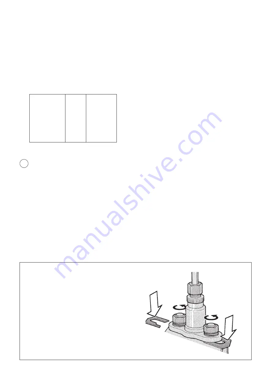
If necessary, adjust stroke by fitting/removing
shims under the flange bushing.
If the pump piston stroke is too early, fit thicker
shims. Fit thinner ones if the stroke is delayed.
Lift from basic circle at start of measuring
1.
Set no. 1 pump piston to its bottom position. Zero-
set the dial indicator. Remove the relief valve from
the injection pump. Connect the test bench high-
pressure hose to the pump fuel inlet. Plug the
pump fuel outlet.
2.
Start high-pressure feed on the test bench. Check
that the feed pressure is the same as that recom-
mended in the diesel test standards sheet.
Note: The test bench must be disconnected.
1
➀
A. SYNCHRONISATION
Lift from base circle at start
of supply
4.05
±
0.05
mm (initial value)
4.05
±
0.10
mm (check value)
At control voltage U
norm
2.6
±
0.1
V
Injection sequence
1 5 3 6 2 4
Rotational direction
Clockwise
Supply pressure
2.5–2.7 (360–390)
MPa (psi)
Tolerance between cylinders
±
0.50
°
(initial value)
±
0.75
°
(check value)
Pulse wheel cam should match
the impact point on cylinder no. 1
Tolerance
±
0.20
°
(initial value)
±
0.75
°
(check value)
➂
➁


