background image


145

\

\

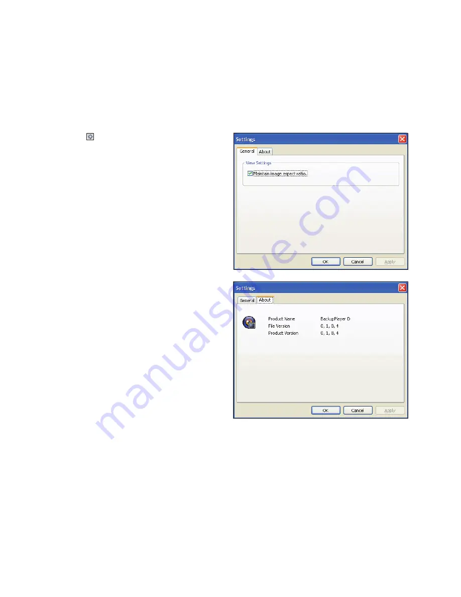
Settings 

Click <   > to configure the Backup Player settings. 

you can check the version of the Backup Player.


i

Maintain image aspect ratio : Preserve the aspect 

ratio of the image. 

if you do not mark this option, the image will be 

adjusted to fit the screen.


i

i frame Play : Only the i frames (key frames) will be 

playback.


i

About : you can check the program information 

including the current version.

Ar

chive V

iewer

Summary of Contents for VT-SRE Spire Elite

Page 1: ...puts of video and audio and recording onto a hard disk drive in real time as well as providing monitoring playback and backup footage in 960H resolution It also provides transferring video and audio data to the networked external devices which allows remote monitoring environment for computers and mobile devices including cell phones The VT SR Series manuals covers the following instructions VITEK...

Page 2: ...etting 70 Audio Setup 71 User Setting 73 Network Setup 76 System Setting 80 Storage 82 Event Setup Introduction 4 4 Safety Instructions 5 What s Included 6 Remote Control at a Glance 7 Change Remote Control ID VT SRL 8 8 VT SRL Overview 9 VT SRL Specifications 10 VT SRL Rear Panel 12 Replacing HDD 16 Basic Layout 17 Connecting to an External Device VT SRE 22 22 VT SRE Overview 23 VT SRE Specificat...

Page 3: ... Mode 96 Search Settings Archiving 102 102 To start the Archive Menu Web Viewer 105 105 What is the Web Viewer 107 Live Screen at a Glance 111 Search 113 Setup Mobile Viewer 129 129 SPIRE DVR Smartphone App Archive Viewer 141 141 Getting Started with the Backup Player 143 Backup Player At a Glance Appendix 146 146 Compatible HDD Specifications 147 Troubleshooting FAQ Warranty 148 148 VITEK Limited...

Page 4: ...fire explosion system failure or electric shock If you need to open the cover consult with an authorized Vitek service technician Do not connect multiple devices to a single power outlet Keep the product away from dust or combustible substances ex propane gas Do not touch product with wet hands Do not insert anything into the vent of the ventilation system Do not apply excessive force when unplugg...

Page 5: ...T AF T ZOOM ZOOM PTZ FOCUS N F RESERVE KEYLOCK AUDIO SEQ LOG ARCHIVE SETUP ALARM PANIC 1 2 3 4 5 6 7 8 9 10 0 ID EXIT MENU ENTER Mouse x1 Remote Control x1 Batteries AAA x2 Power Cable x1 User Manual on USB DC 12V Adaptor x1 Screws Quick Guide Conversion adaptor For 8 channel 16 channel ...

Page 6: ...or playback mode Or used for entering the password SETUP Display the system setup menu ID Set the remote control ID SEQ Switch to sequence mode RESERVE Reserve the current video AUDIO Display the audio channel selection window LOG Display the log list SNAPSHOT Take a snapshot of the video MENU Display the tool bar on the live screen PLAY CONTROLS Used to change the direction or adjust the play spe...

Page 7: ...From MENU SYSTEM SETUP SYSTEM CONTROL DEVICE under the System Setup menu set the REMOTE CONTROLLER ID and press APPLY Select between 00 and 99 For more details refer to SYSTEM SETUP 2 Press the ID button on the remote control The default remote control ID is 00 3 Use the number buttons to provide a two digit ID If you want to enter 01 for instance enter the number 0 and 1 in sequence To check if t...

Page 8: ...MI main monitor output 1 VGA main monitor output and 1 BNC Spot Out H 264 Compression Up to 480fps Live Display 480fps Recording VT SRL916 240 240 VT SRL908 120 120 VT SRL904 Supports both Dynamic and Static IP Addresses Supports 2x internal Hard Drives VT SRL908 VT SRL916 1x HDD VT SRL904 Remote Viewing over the Internet with IE Safari Firefox and Opera Applications for iPhone iPad iPod Touch and...

Page 9: ... HTTP DHCP DDNS 10 100 1000Mbps Thumbnail Calendar Event 1 RS 485 By each camera for different resoultion setting CIF 2CIF D1 960H 4 Levels Low Standard High Highest Continuous Schedule Alarm and Panic Overrides all other recording settings to provide the best quality recording Max 5 seconds Max 180 seconds Adjustable 20x12 Grid with 30 Steps Sensitivity Level Backup player and HDD PC Viewer E mai...

Page 10: ...Y RS485 PAL NTSC h e b f g i a c d a b d HD MONITOR VGA AUX DC 12V ETHERNET VIDEO IN IN 1 IN 2 GND IN 3 IN 4 NO COM NC D D ALARM IN RELAY RS485 PAL NTSC 3 1 7 5 11 9 15 13 4 2 8 6 12 10 16 14 AUDIO IN AUDIO OUT 1 2 3 4 i h g e f c a b d HD MONITOR VGA AUX DC 12V ETHERNET VIDEO IN IN 1 IN 2 GND IN 3 IN 4 NO COM NC D D ALARM IN RELAY RS485 PAL NTSC 3 1 7 5 4 2 8 6 AUDIO IN AUDIO OUT 1 2 3 4 i h g e ...

Page 11: ...pports channels 1 and 2 3 4 Audio input terminal that supports channels 3 and 4 e ALARM IN Alarm input signal port RELAY Relay Terminal output port RS485 Ports for communication with external devices such as PTZ camera and system keyboard f DC 12V Power input port Connect to a 12V adaptor g DIP Switch Select a video type NTSC or PAL h AUDIO OUT Port for speaker connection i HD MONITOR HD monitor v...

Page 12: ...d drive is full or problematic it is possible to replace it yourself 4 Channel Model 1 Remove the screw from the bracket on the bottom of the DVR 2 Hold the HDD bracket with your finger as shown in the figure and pull it to separate it from the DVR ...

Page 13: ... Installation 3 Install the HDD to the bracket see figure When installing the HDD make sure to install in the correct direction 4 Insert the bracket back into the DVR 5 Secure the bracket by fastening the screw ...

Page 14: ...w from each bracket on the bottom of the DVR 2 Hold the HDD bracket with your finger as shown in the figure and pull it to separate it from the DVR 3 Install the HDD to the bracket see figure When installing the HDD make sure to install in the correct direction ...

Page 15: ...15 VT SRL Installation 4 Insert the bracket back into the DVR 5 Secure the bracket by fastening the screw ...

Page 16: ...ended to consult an authorized installer when installing the DVR VGA DC 12V ETHERNET HD MONITOR IN 1 IN 2 GND IN 3 IN 4 NO COM NC D D ALARM IN RELAY RS485 NTSC PAL AUDIO IN AUDIO OUT 1 2 3 4 AUX VIDEO IN DC 12V Power Control Devices Speaker MiC Alarm Sensor Full HD Monitor SPOT 960H Camera Monitor iP Router or HUB ...

Page 17: ...VR For stable operation of the product it is recommended to use the provided adapter 12V 5A Make connection when the power is not applied yet Arrange the cables and be careful not to peel off the cable coating Do not place the power cord under the carpet or rug The power cord is usually earth grounded However even if it s not earth grounded do not modify it on your own for earth grounding Do not p...

Page 18: ...r 2 While pushing insert one end of alarm signal cable into the desired terminal of nO or nC i nO normal Open normally Open but switches to Closed if an alarm out occurs i COM insert the grounding wire i nC normal Closed normally Closed but switches to Open if an alarm out occurs 3 insert the ground signal wire into the hole of the COM port 4 Check to be sure the cable has been inserted properly s...

Page 19: ...t an audio output device such as an amplified speaker to the Audio Out port Storage and Mouse Connection USB Device you can connect and use USB storage devices for backup of recorded video saving snapshots firmware updating importing exporting user configurations in addition the DVR will accept a USB mouse if you need to connect a USB HDD with a high power consumption it is recommended to use a se...

Page 20: ...sword to log in Factory default ADMin 1234 VGA DC 12V ETHERNET HD MONITOR IN 1 IN 2 GND IN 3 IN 4 NO COM NC D D ALA RM IN REL AY RS485 NTS C PAL AUDIO IN AUDIO OUT 1 2 3 4 AUX VIDEO IN Local PC Local PC Broadband router or hub Camera HD MONITOR VGA AUX DC 12V ETHERNET VIDEO IN IN 1 IN 2 GND IN 3 IN 4 NO COM NC D D ALARM IN RELAY RS485 PAL NTSC 3 1 7 5 11 9 15 13 4 2 8 6 12 10 16 14 AUDIO IN AUDIO ...

Page 21: ...ITOR VGA AUX DC 12V ETHERNET VIDEO IN IN 1 IN 2 GND IN 3 IN 4 NO COM NC D D ALARM IN RELAY RS485 PAL NTSC 3 1 7 5 11 9 15 13 4 2 8 6 12 10 16 14 AUDIO IN AUDIO OUT 1 2 3 4 HD MONITOR VGA AUX DC 12V VIDEO IN IN 1 IN 2 GND IN 3 IN 4 NO COM NC D D ALARM IN RELAY RS485 PAL NTSC 3 1 7 5 11 9 15 13 4 2 8 6 12 10 16 14 AUDIO IN AUDIO OUT 1 2 3 4 HD MONITOR VGA AUX ETHERNET VIDEO IN IN 1 IN 2 GND IN 3 IN ...

Page 22: ...at 480 fps 400 fps in real time Up to 16 channels of 960H camera videos can be saved at maximum 480 NTSC 400 PAL fps Simultaneous recording and playback of maximum 16 channels at 120 fps 960H Supports H 264 HP High Profile CODEC Auto alarm feature with self diagnostics on the system HDD S M A R T system temperature network error FAN error etc Supports dual streaming for remote access service Suppo...

Page 23: ... Remote Control TCP IP HTTP DHCP DDNS 1 LAN 1 WAN 10 100 1000Mbps Calendar Event 1 RS 485 By each camera for different resoultion setting CIF 2CIF D1 960H 4 Levels Low Standard High Highest By hour by day by recording mode By alarm By Ch Overrides all other recording settings to provide the best quality recording Max 5 seconds Max 180 seconds Adjustable 20x12 Grid with 10 Steps Sensitivity Level B...

Page 24: ... c d HD MONITOR VGA eSATA USB LAN DOWNLINK WAN UPLINK VIDEO IN RS 232 RELAY ALARM IN 485 485 GND GND NC2 GND IN3 IN4 COM1 NO1 COM2 GND 232TX 232RX IN1 IN2 RS 485 AUDIO OUT AUX SPOT OUT AUDIO IN 1 AUDIO IN 2 AUDIO IN 3 AUDIO IN 4 AUDIO IN 15 16 13 14 11 12 9 10 7 8 5 6 3 4 1 2 P A L N T S C DC 12V l k j i h g e f a b c d AUDIO IN CH1 CH2 CH4 CH3 CH1 CH2 CH4 CH3 AUX SPOT OUT VIDEO IN VIDEO OUT PAL N...

Page 25: ...r connection to the Internet router or hub LAN DOWN LINK Port for connecting the dedicated network device Do not share it with other device h USB Used for connecting USB storage or mouse i eSATA Connection port for external eSATA storage j HD MONITOR HD monitor video output port k VGA VGA monitor video output port l ALARM IN Alarm input signal port RELAY 1 2 Relay Terminal output port RS485 Ports ...

Page 26: ...main unit 4 Once the bracket is separated remove screws on both sides of the HDD drive to be separated and replaced 5 Install the new HDD and fix screws on both sides When installing the HDD make sure to install in the correct direction VGA N T S C P A L LAN DOW NLIN K WAN UPL INK USB eSAT A HD MON ITOR RS 23 2 RELAY ALAR M IN 485 485 GND GND NC2 GND IN3 IN4 COM1 NO1 COM2 GND 232TX 232RX IN1 IN2 R...

Page 27: ...r back on the unit and tighten screws on its rear and both sides VGA N T S C P A L LAN DOW NLIN K WAN UPL INK USB eSAT A HD MON ITOR RS 23 2 RELAY ALAR M IN 485 485 GND GND NC2 GND IN3 IN4 COM1 NO1 COM2 GND 232TX 232RX IN1 IN2 RS 48 5 AUD IO OUT AUX SPO T OUT AUD IO IN 1 AUD IO IN 2 AUD IO IN 3 AUD IO IN 4 AUDIO IN VIDEO IN 15 16 13 14 11 12 9 10 7 8 5 6 3 4 1 2 DC 12V b a ...

Page 28: ... RS 232 RELAY ALA RM IN 485 485 GND GND NC2 GND IN3 IN4 COM1 NO1 COM2 GND 232TX 232RX IN1 IN2 RS 485 AUDIO OUT AUX SPOT OUT AUDIO IN 1 AUDIO IN 2 AUDIO IN 3 AUDIO IN 4 AUDIO IN VIDEO IN 15 16 13 14 11 12 9 10 7 8 5 6 3 4 1 2 N T S C P A L DC 12V Mouse POS DC 12V Power Control Devices Sensor Alarm Speaker SPOT Monitor sSATA Storage SPOT Monitor MiC Monitor 960H Camera iP Router or HUB ATM Access Co...

Page 29: ...en the power is not applied yet Arrange up the cables and be careful not to peel off the cable coating Do not place the power cord under the carpet or rug The power cord is usually earth grounded However even if it s not earth grounded do never modify it on your own for earth grounding Do not insert multiple devices in a single power socket Otherwise it may cause a power overload For stable power ...

Page 30: ...alarm signal cable into the desired terminal of nO or nC i nO normal Open normally Open but switches to Closed if an alarm out occurs i COM insert the grounding wire i nO normal Open normally Open but switches to Closed if an alarm out occurs 3 insert the ground signal wire into the hole of the COM port 4 Check to be sure the cable has been inserted properly stop pushing and gently pull the cable ...

Page 31: ...pplicable PTZ camera or keyboard controller Audio Device Connection Connect an audio input device such as a microphone to the rear Audio in port connect an audio output device such as an amplified speaker to the Audio Out port HD MONITOR eSATA USB LAN DOWNLINK WAN UPLINK VIDEO IN RS 232 RELAY ALARM IN 485 485 NC2 GND IN2 IN3 COM1 NO1 COM2 GND 232TX 232RX IN0 IN1 RS 485 AUDIO OUT SPOT OUT AUX AUDIO...

Page 32: ...h power consumption it is recommended to use a separate power source for that HDD HD MONITOR eSATA USB LAN DOWNLINK WAN UPLINK VIDEO IN RS 232 RELAY ALARM IN 485 485 NC2 GND IN3 IN4 COM1 NO1 COM2 GND 232TX 232RX IN1 IN2 RS 485 AUDIO OUT AUX SPOT OUT AUDIO IN 1 IN 1 AUDIO IN 2 IN 2 AUDIO IN 3 IN 3 IN 3 AUDIO IN 4 IN 4 IN 4 AUDIO IN 15 16 13 14 11 12 9 10 7 8 5 6 3 4 1 2 P A L N T S C VGA DC 12V 5 6...

Page 33: ...N UPLINK USB eSA TA HD MONITOR RS 232 REL AY ALA RM IN 485 485 GND GND NC2 GND IN3 IN4 COM1 NO1 COM2 GND 232TX 232RX IN1 IN2 RS 485 AUDIO OUT AUX SPOT OUT AUDIO IN 1 AUDIO IN 2 AUDIO IN 3 AUDIO IN 4 AUD IO IN VIDEO IN 15 16 13 14 11 12 9 10 7 8 5 6 3 4 1 2 N T S C P A L DC 12V Local PC Local PC Broadband router or hub Camera HD MONITOR eSATA USB VIDEO IN RS 232 RELAY ALARM IN 485 485 NC2 GND IN3 I...

Page 34: ...IN0 IN1 RS 485 AUDIO OUT AUX SPO T OUT AUDIO IN 1 AUDIO IN 2 AUDIO IN 3 AUDIO IN 4 AUD IO IN VIDEO IN 15 16 13 14 11 12 9 10 7 8 5 6 3 4 1 2 N T S C P A L DC 12V Local PC Local PC Remote PC internet ADSL modem Broadband router Smart Phone Direct Connection internet HD MONITOR eSATA USB VIDEO IN RS 232 RELAY ALARM IN 485 485 NC2 GND IN2 IN3 COM1 NO1 COM2 GND 232TX 232RX IN0 IN1 RS 485 AUDIO OUT AUX...

Page 35: ...35 Notes Notes ...

Page 36: ...fps in real time Up to 16 channels of 960H camera videos can be saved at maximum 480 NTSC 400 PAL fps Simultaneous recording and playback of maximum 16 channels at 120 fps 960H Supports H 264 HP High Profile CODEC Auto alarm feature with self diagnostics on the system HDD S M A R T system temperature network error FAN error etc Supports dual streaming for remote access service Supports HDD extensi...

Page 37: ... Remote Control TCP IP HTTP DHCP DDNS 1 LAN 1 WAN 10 100 1000Mbps Calendar Event 1 RS 485 By each camera for different resoultion setting CIF 2CIF D1 960H 4 Levels Low Standard High Highest By hour by day by recording mode By alarm By Ch Overrides all other recording settings to provide the best quality recording Max 5 seconds Max 180 seconds Adjustable 20x12 Grid with 10 Steps Sensitivity Level B...

Page 38: ... 1 2 3 4 5 6 7 8 VIDEO IN LOOP OUT RELAY NO3 NO1 COM3 COM1 COM4 COM2 NC4 NC2 IN5 IN1 IN6 IN2 GND GND IN7 IN3 IN8 IN4 GND ARI ALARM IN n m l k j i h o g f e a b c d RELAY NO3 NO1 COM3 COM1 COM4 COM2 NC4 NC2 IN5 IN1 IN6 IN2 GND GND IN7 IN3 IN8 IN4 GND ARI ALARM IN RELAY NO7 NO5 COM7 COM5 COM8 COM6 NC8 NC6 IN3 IN9 IN14 IN10 GND GND IN15 IN11 IN16 IN12 GND PANIC ALARM IN RS 485_1 ALARM OUT RS 485_2 D ...

Page 39: ...onnecting USB storage or mouse n WAN UPLINK Network port for connection to the Internet router or hub LAN DOWN LINK Port for connecting the dedicated network device Do not share it with other device o ALARM IN Alarm input signal port ALARM OUT Alarm out signal port TTL RELAY Relay Terminal output port RS485 Ports for communication with external devices such as PTZ camera and system keyboard RS232 ...

Page 40: ... illustrations are based on the 16 channel model 1 Remove the 2 screws on both ends of DVR 2 Pull the front faceplate of the unit forward to separate it 3 Hold the middle section of HDD bracket s handle with index finger and pull it forward while supporting the bracket handle with your thumb and middle finger as shown in the illustration a b ...

Page 41: ...nstall a new HDD and fasten the 4 screws back to both ends of the bracket When installing HDD make sure to install in the correct direction 6 Push the bracket with new hard drive installed back into the main unit until it is completely inserted 7 Assemble the front panel back to the unit 8 Fasten the 2 screws on both ends of the main unit DVR Assembly Direction ...

Page 42: ...4 IN10 GND GND IN15 IN11 IN16 IN12 GND PANIC ALARM IN RS 485_1 ALARM OUT RS 485_2 D D D D GND GND RX TX AO5 AO1 AO6 AO2 GND GND AO7 AO3 AO8 AO4 RS 232 HD MONITO R VGA eSATA USB LAN DOWNLINK WAN UPLINK AUX NTS C PAL 100 240V 50 60 Hz ON OFF AUDIO IN VIDE O IN LOO P OUT SPO T 1 SPO T 2 SPO T 3 SPO T 4 1 2 5 6 9 10 13 14 3 4 7 8 11 12 15 16 1 2 AUDIO OUT Mouse POS Control Devices Sensor Alarm Full HD...

Page 43: ...COM2 NC4 NC2 IN5 IN1 IN6 IN2 GND GND IN7 IN3 IN8 IN4 GND ARI ALARM IN RELAY NO7 NO5 COM7 COM5 COM8 COM6 NC8 NC6 IN3 IN9 IN14 IN10 GND GND IN15 IN11 IN16 IN12 GND PANIC ALARM IN RS 485_1 ALARM OUT RS 485_2 D D D D GND GND RX TX AO5 AO1 AO6 AO2 GND GND AO7 AO3 AO8 AO4 RS 232 LAN DOWNLINK WAN UPLINK eSATA USB HD MONITOR AUX VGA NTSC PAL 1 2 3 4 5 6 7 8 9 10 11 12 13 14 15 16 1 2 1 2 5 6 9 10 13 14 3 ...

Page 44: ... 485_2 D D D D GND GND RX TX AO5 AO1 AO6 AO2 GND GND AO7 AO3 AO8 AO4 RS 232 LAN DOWNLINK WAN UPLINK eSATA USB HD MONITOR AUX VGA NTSC PAL 1 2 3 4 5 6 7 8 9 10 11 12 13 14 15 16 1 2 1 2 5 6 9 10 13 14 3 4 7 8 11 12 15 16 AUDIO OUT ON OFF 100 240V 50 60 Hz SPOT 1 SPOT 2 SPOT 3 SPOT 4 VIDEO IN LOOP OUT NO1 COM3 COM1 COM4 COM2 NC4 NC2 NO5 COM7 COM5 COM8 COM6 NC8 NC6 RS 485_1 RS 485_2 D D D GND GND TX ...

Page 45: ...AO6 AO2 GND GND AO7 AO3 AO8 AO4 RS 232 LAN DOWNLINK WAN UPLINK eSATA USB HD MONITOR AUX VGA NTSC PAL 1 2 3 4 5 6 7 8 9 10 11 12 13 14 15 16 1 2 1 2 5 6 9 10 13 14 3 4 7 8 11 12 15 16 AUDIO OUT ON OFF 100 240V 50 60 Hz SPOT 1 SPOT 2 SPOT 3 SPOT 4 VIDEO IN LOOP OUT NO1 COM3 COM1 COM4 COM2 NC4 NC2 NO5 COM7 COM5 COM8 COM6 NC8 NC6 RS 485_1 RS 485_2 D D D GND GND TX AO1 AO6 AO2 GND GND AO7 AO3 AO8 AO4 1...

Page 46: ... D GND GND TX AO1 AO6 AO2 GND GND AO7 AO3 AO8 AO4 1 2 3 4 5 6 7 8 9 10 11 12 13 14 15 16 1 2 1 2 5 6 9 10 13 14 3 4 7 8 11 12 15 16 LOOP OUT AUDIO IN AUDIO IN RELAY RELAY RELAY NO3 NO3 NO3 NO1 NO1 NO1 NO1 COM3 COM3 COM3 COM3 COM1 COM1 COM1 COM1 COM4 COM4 COM4 COM4 COM2 COM2 COM2 COM2 NC4 NC4 NC4 NC4 NC2 NC2 NC2 NC2 IN5 IN5 IN5 IN1 IN1 IN1 IN6 IN6 IN6 IN2 IN2 IN2 GND GND GND GND GND GND IN7 IN7 IN7...

Page 47: ...RM IN RS 485_1 ALARM OUT RS 485_2 D D D D GND GND RX TX AO5 AO1 AO6 AO2 GND GND AO7 AO3 AO8 AO4 RS 232 LAN DOWNLINK WAN UPLINK eSATA USB HD MONITOR AUX VGA NTSC PAL 1 2 3 4 5 6 7 8 9 10 11 12 13 14 15 16 1 2 1 2 5 6 9 10 13 14 3 4 7 8 11 12 15 16 AUDIO OUT ON OFF 100 240V 50 60 Hz SPOT 1 SPOT 2 SPOT 3 SPOT 4 VIDEO IN LOOP OUT NO1 COM3 COM1 COM4 COM2 NC4 NC2 NO5 COM7 COM5 COM8 COM6 NC8 NC6 RS 485_1...

Page 48: ...T 4 VIDEO IN LOOP OUT NO1 COM4 COM2 NO5 RS 485_2 D AO3 AO4 3 4 7 8 11 12 15 16 AUDIO IN AUDIO IN RELAY RELAY RELAY NO3 NO3 NO3 NO1 NO1 NO1 NO1 COM3 COM3 COM3 COM1 COM1 COM1 COM4 COM4 COM4 COM2 COM2 COM2 NC4 NC4 NC4 NC2 NC2 NC2 IN5 IN5 IN5 IN1 IN1 IN1 IN6 IN6 IN6 IN2 IN2 IN2 GND GND GND GND GND GND IN7 IN7 IN7 IN3 IN3 IN3 IN8 IN8 IN8 IN4 IN4 IN4 GND GND GND ARI ARI ARI ALARM IN ALARM IN ALARM IN RE...

Page 49: ...49 Notes Notes ...

Page 50: ...nd provide the password The default USER ID is ADMIN and the PASSWORD is 1234 3 Click OK For safe and secure use of the product change the password after purchasing Log Out To prevent unauthorized access it is recommended to log out when you leave the screen 1 In the live monitoring screen click MENU in the bottom left corner of the screen to LOG OUT or press the LOGOUT button on the remote contro...

Page 51: ...emote control If you turn off the system in an abnormal manner such as removing the power cord while the system is in operation the disk can be damaged causing data loss and shortened life cycle of the disk Shutdown turns off Disk and Operations The DVR will ask to disconnect power to the unit on the SRP turn the power switch next to the 110 power cord input to OFF ...

Page 52: ...sed in the video window Item Description Camera ID Show the camera ID Record Mode Icons Displayed if an event recording is reserved Continuous Recording Alarm Recording Motion Recording Panic Emergency Recording Audio I O Icons Audio Output Motion Detection Icon Motion is detected by the connected camera Video Window Quick Menu Status Bar Timeline ...

Page 53: ...n the screen PTZ Launches the PTZ control screen Zoom Digital Zoom Quick Log Displays the log list of the recent recording events Audio Channel Selection Button Select the audio input to listen to Panic Record Start stop panic recording Alarm Indicator Turns on if a predetermined alarm event occurs Network Connection Status Click this to view the current users remotely logged into the DVR and to c...

Page 54: ... timeline Navigation through Timeline Navigate through the timeline You can also use the mouse wheel Timeline Bar Displays the recording data with time The color of each bar indicates the following Green Continuous Recording Red Alarm Recording Blue Motion Recording Yellow Panic Recording Quick Menu Right click on a channel to display a quick menu popup window Item Description Channel No Displays ...

Page 55: ...e SEQ button on the remote control You can configure the sequence settings in SEQUENCE For details refer to Sequence page 64 Controlling a PTZ To control a PTZ camera select the channel then click PTZ button on the status bar or press the PTZ button of the remote control to In PTZ mode use the directional buttons to control the PTZ Use ZOOM FOCUS IRIS PRESET and SCAN TOUR to make adjustments to PT...

Page 56: ... channel to zoom in out i i Zoom out the current enlarged image step by step i i Enlarge the current image step by step i i Zoom Box Use the yellow box to move to or select a desired zooming area i i Exit the zooming screen and return to the live screen Digital zooming magnifies the video image digitally and produces enlarged images that may not be sharp and clear For sharper and clearer magnifica...

Page 57: ... FULL SCREEN When switching the DVR display mode to view one channel Single Split it produces the selected channel s audio Check the Alarm Status You can check alarms and events from each camera and the system Click OK to close the window Check the Network Status Shows the connection status of cameras and network devices Click OK to close the window For more information refer to Network Status pag...

Page 58: ... the SnAPSHOT button of the remote control 2 Connect a storage device and click the ExPORT button To save the captured image to the built in HDD press the RESERVE button Saved image can be found in the Archive Reserved data management and can be backed up later Page 101 3 Enter the TAg nAME and MEMO and press BURn or ERASE BURn button i A progress bar appears and indicates the progress of exportin...

Page 59: ...e to the System Setup menu How to use the mouse ENTER ENTER How to use the remote control 1 MENU ENTER SEARCH SETUP MENU ENTER ENTER ENTER SEARCH SETUP MENU ENTER ENTER How to use the remote control 2 RCH SETUP System Setting ...

Page 60: ...k APPLY at the bottom of the screen 5 When done press the EXIT button on the remote control or click CLOSE in the lower screen A confirmation message appears and you will return to the previous menu For the SRE and SRP models camera titles can be up to 16 characters combining numbers and upper lower case letters no spaces For the SRL model camera titles can be up to 8 characters Image Setup You ca...

Page 61: ... SySTEM SETUP CAMERA select COVERT SETUP 2 Use the EnTER buttons on the remote control or use the mouse to select a covert channel s for a specific user group i ADMin MAnAgER USER Set them to On The selected channel s will be covert from the applicable user account i LOg OUT Set it to On When the user logs out the current channel will be set to a covert channel 3 To apply the change click APPLy in...

Page 62: ...rs and you will return to the previous menu The motion detection sensitivity may differ depending on the characteristics of the connected camera or the installation environment Motion Area Setup From the motion sensor window click EDIT AREA to display the area setup screen 1 Click EDIT AREA to move to the motion area setup screen 2 If using the remote control press the ENTER button to initiate the...

Page 63: ...an cause severe noise which can trigger motion events too often If unwanted events occur frequently at night you may want to reduce the motion sensitivity for the nighttime setting PTZ Settings Set the camera ID protocol baud rate and PTZ control speed for each channel 1 From MENU SYSTEM SETUP CAMERA select PTZ SETUP 2 Use ENTER buttons of the remote control or mouse to set protocol and baud rate ...

Page 64: ...he previous menu PRIVACY MASK SRE SRP ONLY Allows users to block out specific areas of camera image 1 Select PRIVACY MASK from MEnU SySTEM SETUP CAMERA 2 Set the activation of each channel in the ACTiVATiOn tab ACTiVATiOn Set to on for each camera channel that will utilize the featureMARK Turns on or off the detection indicator to be displayed on the screen MASK COLOR Choose the Privacy Mask color...

Page 65: ...N The status bar will be displayed at all times 5 SEC 1 MIN If no mouse movement is detected from 5 seconds to 1 minute the status bar will disappear i i TIMELINE ON FULL SCREEN MODE shows hides the timeline in full screen mode AUTO HIDE move the cursor to the right margin to display the timeline Move the cursor to the left to hide the timeline ALWAYS ON The timeline will be displayed at all times...

Page 66: ...x1024 1280x720 1920x1080 5 To apply the change click APPLy in the bottom of the screen 6 When done press the ExiT button on the remote control or click CLOSE in the lower screen The confirmation message appears and you will return to the previous menu Sequence Configure the sequence feature 1 From MEnU SySTEM SETUP DiSPLAy select SEQUEnCE 2 Use the EnTER buttons on the remote control or use the mo...

Page 67: ... VIEW TYPE 6 When the SEQUENCE SETUP dialog appears select a split mode that you want to add from VIEW TYPE 7 When the selected split mode is displayed on VIEW CONFIGURE select a channel you want to display in each split screen 8 Click CONFIRM The set sequence mode is confirmed and will be added to the Sequence list 9 When done click CLOSE in the bottom of the screen After the sequence type is sav...

Page 68: ...t menu Then select MODIFY 6 When done click CLOSE to close the window 7 To apply your changes click APPLY SPOT OUT You can configure the Spot Out to display a Live channel in various live view types depending on model From MENU SYSTEM SETUP DISPLAY select SPOT OUT 1 Use ENTER button of the remote control or mouse to edit Spot Out properties select the name in the LIST i i SPOT TITLE Name the Spot ...

Page 69: ...e and configuration and click CONFIRM button 5 Complete adding and click CLOSE to close the edit window 6 To apply your changes click APPLY button To edit or delete View Type of the SPOT Output 1 Select the SPOT Output from the list 2 The EDIT window appears click MODIFY button 3 When the View Type selection window appears select the desired View Type to be edited or deleted and press ENTER button...

Page 70: ... RECEIVE NETWORK AUDIO enables audio reception from a remote client PC 3 To apply the change click APPLY in the bottom of the screen 4 When done press the EXIT button on the remote control or click CLOSE in the lower screen The confirmation message appears and you will return to the previous menu Buzzer Enables disables a beeping sound when you manipulate the remote control 1 From MENU SYSTEM SETU...

Page 71: ...the remote control or a mouse and move to a desired item Then press ENTER to select the item i i USER ID enter the user ID using the virtual keyboard 10 characters max case sensitive i i PASSWORD With the virtual keyboard enter the password 8 characters max case sensitive i i GROUP select a group that the user belongs to ADMIN MANAGER USER i i EMAIL Type in the e mail address to which you will rec...

Page 72: ...ENU SYSTEM SETUP USER select GROUP AUTHORITY 2 Use the ENTER buttons or use the mouse to set the permissions for both MANAGER and USER groups i i SEARCH i i ARCHIVING i i SYSTEM SETUP i i RECORD SETUP i i EVENT ACTION CONTROL i i LISTEN TO AUDIO i i REMOTE LOG IN i i SHUTDOWN The ADMIN account is the master account and has ALL permissions 3 To apply the change click APPLY in the bottom of the scre...

Page 73: ...s of the secondary DNS server i i RTSP SERVICE PORT port number that the remote client receives the DVR video from i i WEB SERVICE PORT port number used for connecting to the DVR i i PORT FORWARDING If the DVR is connected to a router that supports UPnP Universal Plug and Play clicking PORT FORWARDING will automatically forward the port in your router If the router does not support UPnP you must c...

Page 74: ...uccessfully the DVR ADDRESS will be added automatically i i DDNS CONNECTION TEST Test connection of DVR to DDNS server 3 To apply the change click APPLY in the bottom of the screen 4 When done press the EXIT button on the remote control or click CLOSE in the lower screen The confirmation message appears and you will return to the previous menu Email Configure and test an email address to use for s...

Page 75: ...dicates the web service port used for remote access For remote access the web service port must be port forwarded in the router i i DDNS UPDATE STATUS Shows if the DDNS address was successfully registered to the DDNS server Press to try to register the DDNS address forcibly i i EXTERNAL IP ADDRESS Indicates the public IP address of the DVR which can be used to access the DVR from a remote network ...

Page 76: ...mat i i TIME SERVER obtain the current time from the time server Click to get the current time i i AUTO TIME SYNC automatically synchronize the time with the time server at a specific time i i SYNC AT Set the time to sync with the time server i i TIMEZONE specify the GMT standard time for your local area i i DST You can set up or release the DST Daylight Saving Time Both TIME SERVER and TIME SYNC ...

Page 77: ...s or get the system information from other device SAVE Store the DVR settings to a USB storage device LOAD Apply the settings of the USB storage device to the DVR i i PASSWORD The DVR will prompt the user for a password when accessing any of the menus log out system settings record settings backup and search If it is set to Off note that the ADMIN account is only effective and access to all menus ...

Page 78: ...5 When the confirmation message appears click OK 6 The progress bar displays the progress of the firmware upgrade 7 When the upgrade is complete reboot the system During the updating never turn off the DVR forcibly or disconnect the USB storage device to avoid serious damage to the product or data If required consult your nearest service center for professional assistance ...

Page 79: ...n case the site has multiple DVRs of the same model 1 From MENU SYSTEM SETUP SYSTEM select CONTROL DEVICE 2 Use the ENTER buttons on the remote control or use the mouse to set the connection options for the control device i i SYSTEM ID Set the ID of the DVR so that the keyboard controller can identify i i PROTOCOL Set up the protocol of the keyboard controller i i BAUD RATE Specify the RS485 commu...

Page 80: ...ATUS Read the S M A R T information of the disk and displays disk status NORMAL The disk is in a normal state CHECK The disk has an error check the disk and or the connection cables If you leave the problem unresolved it may affect the recording it is recommended that you replace the disk immediately ERROR The disk has failed and should be replaced immediately Contact the retailer or service techn...

Page 81: ... and set the overwrite options You can also format the HDD 1 From MENU SYSTEM SETUP STORAGE select DISK OPERATIONS 2 Use the ENTER buttons on the remote control or use the mouse to set the operation conditions of the disk i i DISK WRITE MODE If it is set to OVERWRITE the oldest existing data will be overwritten by the newest recording data This occurrs once the HDD is full If the option is set to ...

Page 82: ...ng it is recommended that you replace the disk immediately ERROR The disk has failed and should be replaced immediately Contact the retailer or service technician i i S M A R T CHECK INTERVAL Specify the S M A R T check interval Click CHECK NOW to start checking 3 To apply the change click APPLY in the bottom of the screen 4 When done press the EXIT button on the remote control or click CLOSE in t...

Page 83: ...Alarm Output 8 Alarm Input 1 Alarm Input 4 Alarm Input 16 Relay 8 ON OFF Schedule You can activate or turn off the alarm output as scheduled 1 Use the ENTER buttons on the remote control or use the mouse to select a DATE for the schedule 2 Drag the mouse to resize the cell or use the on the buttons to move to the cell then press ENTER 3 Select a desired alarm output mode i i ON The alarm output is...

Page 84: ...s pressed 5 300 SEC Keep the buzzer out for a specified time Display If an event occurs you can configure the video popup or a popup message to notify the user i i VIDEO POPUP Display the video channel that is synchronized with the event on a single split screen Set the DURATION of the single split screen TRANSPARENT Keep the video popup displayed as long as the event occurs UNTIL KEY Keep the vid...

Page 85: ... can specify the name of the alarm sensor i i OPERATION You can specify the type of the alarm sensor N O Normal Open Normally the sensor is left Open If the sensor switches to Close an event will be triggered N C Normal Close Normally the sensor is left Close If the sensor switches to Open an event will be triggered i i LINKED CAMERA Set the camera to sync with the alarm sensor if it is triggered ...

Page 86: ...sting presets i i VIDEO POPUP Enables the video popup if motion is detected by the motion sensor i i EMAIL Select to send an email if motion is detected by the motion sensor 3 To apply the change click APPLY in the bottom of the screen 4 When done press the EXIT button on the remote control or click CLOSE in the lower screen The confirmation message appears and you will return to the previous menu...

Page 87: ...ISK FULL EVENT if you set the disk write mode to ONCE this event occurs when the disk is full 100 i i DISK SPACE EXHAUSTED EVENT Event that is triggered if the disk is almost full Click to specify the threshold percentage of usage to trigger the event i i S M A R T EVENT Occurs if the disk encounters a S M A R T error i i NO DISK EVENT Occurs due to a disk failure or cable problem To detect the di...

Page 88: ... EVENT Network i i TROUBLE IN INTERNET CONNECTION Occurs if the Internet connection to the DVR fails If you do not want to connect the DVR to the network leave the ACTION item blank i i FAIL IN REMOTE LOGIN This event occurs if a remote client fails to log in due to an invalid ID or password You can specify the number of failed log in attempts by selecting the drop down i i FAIL IN DDNS UPDATE Thi...

Page 89: ...s detected by the motion sensor i i BUZZER Enables the buzzer if motion is detected by the motion sensor i i VIDEO POPUP Enables the video popup if motion is detected by the motion sensor i i EMAIL Select to send an email if motion is detected by the motion sensor 3 To apply the change click APPLY in the bottom of the screen 4 When done press the EXIT button on the remote control or click CLOSE in...

Page 90: ... settings for the DVR Only authorized users can access the Record Setup menu To start the Record Setup menu How to use the mouse ENTER ENTER How to use the remote control MENU ENTER SEARCH SETUP MENU ENTER ENTER ENTER SEARCH SETUP MENU ENTER ENTER ...

Page 91: ...detected or an alarm event occurs i inTEnSiVE MOTiOn RECORD DVR will record continually in normal quality However the quality will switch to high if motion is detected i inTEnSiVE ALARM RECORD DVR will record continually in normal quality However the quality will switch to high if an alarm event occurs i inTEnSiVE MOTiOn ALARM RECORD DVR will record continually in normal quality However the qualit...

Page 92: ...f you want to configure every day with the same record settings set the SCHEDULE MODE to DAILY 2 Click a time cell from which you want to edit the SIZE FPS Quality and drag it to a desired cell Or use the buttons on the remote control to move to the cell and press ENTER Then use the buttons to move to a desired cell and press ENTER again 3 When the cell selection is complete the SIZE FPS QUALITY t...

Page 93: ...LY in the bottom of the screen 5 When done press the EXIT button on the remote control or click CLOSE in the lower screen The confirmation message appears and you will return to the previous menu Motion Recording You can configure the settings of motion recording time recording size frame rate per second and quality 1 From the MENU RECORDING menu select MOTION RECORDING 2 Use the buttons on the re...

Page 94: ...hen done press the ExiT button on the remote control or click CLOSE in the lower screen The confirmation message appears and you will return to the previous menu Panic Recording you can configure the settings of panic recording time recording size frame rate per second and quality 1 From the MEnU RECORDing menu select PAniC RECORDing 2 Set each item of RESOLUTiOn FPS QUALiTy and use of the AUDiO f...

Page 95: ...itoring How to use the mouse ENTER ENTER How to use the remote control 1 SEARCH SETUP MENU ENTER ENTER ENTER SEARCH SETUP MENU ENTER ENTER MENU ENTER How to use the remote control 2 SEARCH SETUP ENTER To move to the Search menu while in playback mode How to use the mouse ENTER ENTER How to use the remote control SEARCH SETUP Search ...

Page 96: ...ATION MODE i i Dark Green Continuous Recording i i Red Alarm Recording i i Blue Motion Recording i i Yellow Panic Recording 4 Click to move to a desired start time in the time bar Use the buttons at the bottom of the status bar as well i i Recall the recording data i i Zoom in on the timeline i i Zoom out on the timeline i i Move to a previous time on the time bar i i Move to a previous time on th...

Page 97: ...irst date of recording is automatically selected i i LAST The last date of recording is automatically selected i i CHANNEL Select a channel to search for i i DATE TIME Specify the search date and time The menus available differ depending on the selected interval mode i i INTERVAL Select a time interval of the thumbnail view 3 Double click a desired play time in the recording data bar or double cli...

Page 98: ...ist 5 Press the SEARCH button The search results will be listed as shown i i TYPE displays the event type i i TIME displays the recording start time i i CONTENTS shows the details of the event found i i ORDER BY If you select OLDEST the list will be sorted with the earliest one on top 6 Double click a desired event or click PLAY in the lower right corner to move to the play screen 7 If you want to...

Page 99: ... bar in the timeline indicates the current point of playback Double click a desired point in the timeline to start playing the video from that point Click and drag to specify a seleted time period right click the selected time range to Export Archive Event Search or to Reserve Data Menu split screen selection menu For more information about how to use each button refer to Using the status bar in t...

Page 100: ...the video forward Fast Forward The video will be played forward at the speed of x2 4 8 16 32 64 in this order Zoom In Move to the zoom in out screen of the selected channel Snapshot Capture the current live video and save it as a jpeg You can save the captured snapshot to the HDD or export it to an external USB memory device While taking a snapshot the current video will stop playing Start end boo...

Page 101: ... 4 To stop the bookmarking click BOOKMARK 5 To quit the bookmarking click STOP To continue with bookmarking just click CONTINUE 6 Click RESERVE You can export the reserved data to a connected storage device using the ARCHIVE menu What is the RESERVE function With the RESERVE function you can reserve data even in overwrite mode This is useful if you want to backup data but you have no backup device...

Page 102: ...the start and end time 4 Mark the LOG and CODEC checkboxes to include these with the archived media NOTE To view the video on a PC you will need the CODEC 5 Click QUERY The results will be listed in ARCHIVING INFO The maximum backup capacity for one time is 20GB If the archiving request exceeds 20GB the end time will be adjusted to within 20GB 6 To export to a storage device insert USB to the DVR ...

Page 103: ... a storage device connect it to the DVR and click EXPORT 5 If you want to delete the reserved data click next to the list Click CANCEL ALL to cancel reserving the whole page at once 6 To exit the Archive menu click CLOSE Playing the archived data You can play archived data from a USB storage device In addition you can check the details and integrity of the data 1 While in ARCHIVED DATA PLAYBACK co...

Page 104: ...he FTP server address i i PORT enter the port number i i USER NAME enter the FTP user ID i i PASSWORD enter the FTP password i i DIRECTORY specify the archiving path 4 When all information is filled click CONNECTION TEST to check the connection status 5 To apply the change click APPLY in the bottom of the screen 6 When done press the EXIT button on the remote control or click CLOSE in the lower sc...

Page 105: ...connect to the DVR from inside Check the Network Status and verify the IP ADDRESS and WEB SERVICE PORT of the DVR Enter the IP address and web service port in the address bar of the browser Ex http 192 168 1 200 8080 To connect to the DVR from outside Using the IP address Check the Network Status and verify the EXTERNAL IP ADDRESS and WEB SERVICE PORT of the DVR page 45 If using a static external ...

Page 106: ...per warning bar to install the ActiveX If you fail to download the ActiveX control go to Tools Internet Options Security Custom Level Download unsigned ActiveX control and change its setting from Disable recommended to Enable and then click OK 3 Click Install 4 When the installation is complete you will see the live screen ...

Page 107: ...reen of the currently connected DVR c Split Mode Select and switch to a desired split screen mode d Sequence Set the sequence mode switch to the next camera or select the full screen mode e Status Show the connection status of each channel Log Show the log Refresh Time Set the interval at which the DVR Status is refreshed Refresh Load the DVR Status immediately Web Viewer e f d g h c b a ...

Page 108: ...ve Save the live video on the screen Print Print out the current screen Capture Capture the selected image ActiveX Settings Configure the ActiveX settings or specify the default save location for archiving Switching the split mode Click the Switch button to switch the mode as follows 4 split Mode 1 split Mode 9 split Mode 16 split Mode 8 split Mode ...

Page 109: ...celeration 3 If you want to change the saving path click Save Folder and specify a new path User cannot change the save path in Windows Vista 4 Change the streaming settings according to the PC specification and network environment Auto mode is recommended i i Sync If this option is set the audio signal will be synchronized with the video signal However you may encounter a delay due to buffering f...

Page 110: ...e bottom of the screen You can control the operations of a PTZ camera Adjust the focus zooming and iris of the camera You can use the arrow buttons to control the operations of the camera i i Pattern You can configure various settings of the camera including the zooming and movement Applied to some PTZ cameras only i i PRESET Move the camera in a predefined direction i i Swing The camera will move...

Page 111: ...ion b Playback Screen Play the recording data c Split Mode Select and switch to a desired split screen mode d Sequence Set the sequence mode switch to the next camera or select the full screen mode You can turn on off the audio e Play button bar You can control the playback screen f Time Selection Specify the start time of playback g Time Line Indicates the status of the recorded data Web Viewer e...

Page 112: ...1 Select a date that you want to search 2 Check the recording data in the bottom time line and specify the time range for your search You can specify the start time by moving the time bar 3 Click PLAY i i REFRESH Refreshes the search criteria to the current date time i i PLAY Play the searched video i i Backup Archive the recorded video Search by event You can sort the recording data by event 1 Ma...

Page 113: ...ing configured locally the remote setup will be disabled Setup Viewer at a Glance Camera Name the camera title You can name the camera title that is displayed on each channel screen Select a channel to name and provide a new title Then click APPLY to apply it You can enter up to 8 alphanumeric characters for the camera title Web Viewer ...

Page 114: ... menu and make necessary changes When done click APPLY to apply the changes Motion Setting Configure the motion detection feature of each camera Set the detection areas as well as the sensitivity levels for daytime and nighttime Select a channel Set the mask area and activation and specify the daytime range When done click APPLY to apply the changes For information about how to set the motion area...

Page 115: ...115 PTZ Setup To allow the DVR to utilize camera s PTZ functions match the address protocol and baud rate of connected cameras and DVR Web Viewer ...

Page 116: ... item refer to OSD page 65 Monitor Settings You can set the interval of an active sequence Specify the interval and click APPLY to apply it i i SEQUENCE DWELL Switching time from one channel to the next channel in single screen mode i i SPOT DWELL The interval between the view types when displaying the SPOT Out monitoring screen Audio Audio Buzzer You can configure the settings of the voice and au...

Page 117: ...f you want to delete the user click DELETE next to it When done click APPLY to apply the change Group Permission Setting You can grant different user groups different permissions to a specific menu Mark the checkboxes of the menu items accessible by the user group When done click APPLY to apply the changes For more information about the accessible menu items refer to Group Authority page 72 Web Vi...

Page 118: ... network entry refer to IP Setup page 73 DDNS Setting You can configure the DDNS settings Change the DDNS settings and click APPLY to apply the changes Email Setting You can register and test an email address so that an email notification is delivered at a specific interval or if an event occurs Provide the necessary information and click APPLY to apply it For more information refer to Email page ...

Page 119: ...time and date settings refer to Date Time page 76 System Management You can configure the access settings of log in log out and auto logout For more information refer to System Management page 77 System Information You can check the system firmware version disk space and network settings as well as the camera connections and alarm I O Web Viewer ...

Page 120: ...ice Information Internal storage devices physically installed in the DVR and their recording time information are displayed S M A R T Status The detailed S M A R T information of each internal storage device is displayed What is S M A R T This is a sort of HDD self diagnosis tool that detects any error on the system and alerts the user if an error occurs For more information refer to S M A R T on ...

Page 121: ...m output and ON OFF schedule refer to Alarm Out page 82 Event Notification Specify the notification method for BUZZER OUT DISPLAY and EMAIL Specify the buzzer output time display time and email notification and click APPLY to apply the changes For more information about the event notification refer to Event Notification page 84 Web Viewer ...

Page 122: ...ctions refer to Alarm Sensor page 85 Motion Sensor You can set an action to execute when motion is detected When done click APPLY to apply the changes For more information on how to set the motion sensor refer to Motion Sensor page 86 Video Loss You can select an action to execute when there is video loss Select BUZZER and or EMAIL When done click APPLY to apply the changes ...

Page 123: ... to the disk recording network or system happens You can notify the user of the event using the alarm output buzzer OSD popup and email When done click APPLY to apply the changes For more information about how to set the system event refer to System Event page 87 Web Viewer ...

Page 124: ...124 Record Setup Record Setting You can set the recording options for Auto or Manual mode When done click APPLY to apply the changes For more information about how to set each mode refer to Operation Mode page 91 ...

Page 125: ...e rate per second and quality Click next to each item to display the list of values available When you complete the recording size and schedule settings click APPLY to apply your settings For more information about the continuous recording size and schedule refer to Continuous Recording page 92 Web Viewer ...

Page 126: ...ent occurs Click next to each item to display the list of values available Complete setting the SIZE FPS QUALITY AUDIO for the motion recording as well as the SCHEDULE and click APPLY to apply the changes For more information about the motion recording size and schedule refer to Motion Recording page 93 ...

Page 127: ...nt occurs Click next to each item to display the list of values available Complete configuring the SIZE FPS QUALITY AUDIO for the alarm recording as well as the SCHEDULE and click APPLY For more information about the alarm recording size and schedule refer to Alarm Recording page 94 Web Viewer ...

Page 128: ... audio settings Click next to each item to display the list of values available When you have finished click APPLY For more information about the manual record settings refer to Panic Recording page 94 About Click the INFORMATION tab to check the model name of the DVR as well as the web viewer version ...

Page 129: ...n Android Phone Processor 800 MHz or higher Flash 512 MB or higher RAM 512 MB or higher SD Card 4 GB or higher OS 2 0 or higher Processor 1 GHz or higher Flash 512 MB RAM 512 MB SD Card 16 GB or higher OS 2 1 or higher iPhone iPhone 3G iPod touch 3rd Generation iPhone OS 3 1 3 or higher iPhone 3GS or higher iPhone OS 3 2 or higher iPad iPad 1st Generation iPad OS 5 1 1 or higher iPad 1st Generatio...

Page 130: ...Store Enter Vitek SPIRE Viewer in the search bar Install the application on your iPhone The DVR Viewer supports the 1 4 split screen mode To connect to the DVR with EH SPIRE Viewer 1 Select and run the EH SPIRE Viewer 2 Click in the top right corner of the DVR List to select and add a DVR to the list 3 Enter the server name and click Save ...

Page 131: ...ess HTTP port number and RTSP port number and click Save 5 Provide the access ID of the DVR as well as the password 6 Specify the use of the Auto Login 7 Click Save 8 Select the site that you added in the DVR List Mobile Viewer ...

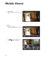
Page 132: ...If connected successfully you will see the screen as shown Split Mode 1 Click any area on the screen The main menu appears at the bottom of the screen 2 Click in the top left corner to switch to 1 split mode click to switch to 4 split mode ...

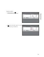
Page 133: ...133 Using the Log View 1 From the main menu click You can check the log of the data stored 2 Select one from Alarm Motion Record Etc and click You will view the log of the related item Mobile Viewer ...

Page 134: ...history of the data stored 2 Select a desired time and date You can use the vertical time bar to specify the start time 3 Click to play the video recorded at the specified time 4 Click any area to display the play bar with which you can control the playing direction and speed of the video ...

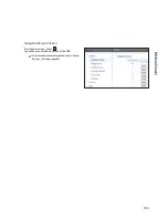
Page 135: ...135 Using the Setup function From the main menu click You will be connected Setup menu of the DVR For details about each displayed item refer to System Settings starting on page 60 Mobile Viewer ...

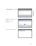
Page 136: ...lication on your Smart Phone The EH SPIRE Viewer supports the 1 4 split screen mode To connect to DVR with nViewer 1 Select and run the nViewer 2 Use the Add button to select and add a site to the list 3 Enter a name for your DVR 4 Provide the IP address HTTP port number and RTSP port number and click Save 5 Provide the access ID of the DVR as well as the password 6 Select whether or not to save t...

Page 137: ... the DVR List Press and hold to display the pop up window 9 Select Connect When connected successfully you will see the screen as shown Split Mode 1 Click any area on the screen The main menu appears at the bottom of the screen Mobile Viewer ...

Page 138: ... click to switch to 4 split mode scroll the screen to the left or right to move to the next camera Using the Log View 1 From the main menu click You can check the log of the data stored 2 Select one from Alarm Motion Record Etc and click You will view the log of related items ...

Page 139: ...ecording data 2 Select a desired time and date You can use the vertical time bar to specify the start time 3 Click to play the video recorded at the specified time 4 Click any area to display the play bar with which you can control the playing direction and speed of the video Mobile Viewer ...

Page 140: ...Mobile Viewer 140 Using the Setup function From the main menu click You will be connected to the setup menu of the DVR For details about each displayed item refer to System Settings starting on page 60 ...

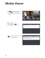
Page 141: ...rowser save the file directly to your PC 2 Insert the USB device containg the archived information into the computer 3 Run the Backup Player 4 Click in the bottom left corner to display the file browser Select the archived file to play You can play the data archived in the DVR You can play the HDD data recorded by the DVR Archive Viewer ...

Page 142: ...Archive Viewer 142 5 Check the integrity of the archived file 6 When done the archived file will be played on the screen ...

Page 143: ...ck time e File Search Open the file that you backed up Capture Capture the current screen Print Print out the current screen f Playback Control Control the playback direction and speed of the current video For more information about how to use the playback control buttons refer to Using the play bar page 69 g Split Mode Switch to 1 4 8 16 split screen mode h Audio Setting Show the sound signal sta...

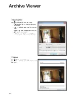
Page 144: ...ame of the current video i i Screen Capture the visible portion of the current video i i Format Select a saving format BMP JPG PNG i i Path Specify the saving path Default location My Documents My Pictures Print Out Click Button to print out the image When the Print window appears check the preview and click Print ...

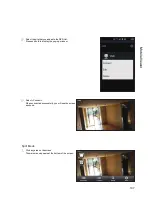
Page 145: ...er i i Maintain image aspect ratio Preserve the aspect ratio of the image If you do not mark this option the image will be adjusted to fit the screen i i I frame Play Only the I frames key frames will be playback i i About You can check the program information including the current version Archive Viewer ...

Page 146: ... 1 5G Can be used SATA2 3 0G Can be used SATA3 6 0G Devices of backward compatibility to SATA2 3 0G can be used Maximum Start up Current 12V 2A or lower Maximum Average Operation Power Consumption 7W or lower Maximum R W Latency Latency Read 13ms Write 13ms or smaller ...

Page 147: ...tching mode Then you will view the video in full screen The 1 1 pixel matching is referred to differently depending on the monitor manufacturer for example JUST SCAN for Samsung ZERO OVERSCAN for LG For details refer to the user manual of the monitor The camera is connected but no image is displayed Make sure that the camera is compatible with the DVR For the compatibility of the cameras contact t...

Page 148: ...ment for a defective product however all related costs including but not limited to shipping and or delivery charges will be the responsibility of the customer If upon return inspection a product is determined to be in good working order or shows evidence of misuse the customer will be respon sible for full payment of the original product purchased as well as the replacement product Beyond the fir...

Page 149: ...149 Notes Notes ...

Page 150: ...28492 Constellation Road Valencia ca 91355 WWW VITEKCCTV COM 888 VITEK 70 ...

Reviews: