background image

48 

D-302756 

2. 

When the PowerMax10-G2 display reads

 [

INSTALLER MODE

]

,


press


OK

I

The screen will now prompt you to enter your installer code. 


OK

I


3. 

Enter your Installer Code. 


CODE


4. 

Press the 

 or 

 button repeatedly and select the [

DEFINE PANEL

option. 


or


5. 

When the PowerMax10-G2 display reads [

DEFINE PANEL

], press 

OK

I


The PowerMax10-G2 display will read [

01:ENTRY DELAY 1

]. 


OK

I


6. 

When the PowerMax10-G2 display reads

 [

01:ENTRY DELAY 1

],

 press


the 


or 

 button repeatedly until the display will read [

12:PANIC ALARM

]. 


or


7. 

Press 

OK

I

 and make the selection and then press 

OK

I

 to confirm. 

The PowerMax10-G2 display will revert to [

12:PANIC ALARM

]. 


OK

I


 SELECT OPTION 

OK

I


You can now press the 

 or 

 button to program any other menu in 

"

DEFINE PANEL

"

 or 

press the 

 button to take you to "

<OK> TO EXIT

"

.


4.8.7 Enabling Latchkey Arming 

Here you determine whether the system can be armed in the latchkey mode. If the system is armed this way, a “latchkey” 
message will be sent to specific telephones upon disarming by a “latchkey user” (users 5-8 or keyfob transmitters 5-8). This 
mode is useful when parents at work want to be informed of a child’s return from school.  
The options are: 

Latchkey ON

 and 

Latchkey OFF

 (default). 

To Enable Latchkey Arming 

1. 

Make sure the system is disarmed and then press the 

 button


repeatedly until the PowerMax10-G2 display reads

 "

INSTALLER MODE

".


2. 

When the PowerMax10-G2 display reads

 [

INSTALLER MODE

]

,


press


OK

I

The screen will now prompt you to enter your installer code. 


OK

I


3. 

Enter your Installer Code. 


CODE


4. 

Press the 

 or 

 button repeatedly and select the [

DEFINE PANEL

option. 


or


5. 

When the PowerMax10-G2 display reads [

DEFINE PANEL

], press 

OK

I


The PowerMax10-G2 display will read [

01:ENTRY DELAY 1

]. 


OK

I


6. 

When the PowerMax10-G2 display reads

  [

01:ENTRY DELAY 1

],

 press


the 


or 

 button repeatedly until the display will read [

20:LATCHKEY

]. 


or


7. 

Press 

OK

I

 and make the selection and then press 

OK

I

 to confirm. 

The PowerMax10-G2 display will revert to [

20:LATCHKEY

]. 


OK

I


 SELECT OPTION 

OK

I


You can now press the 

 or 

 button to program any other menu in 

"

DEFINE PANEL

"

 or 

press the 

 button to take you to "

<OK> TO EXIT

"

.


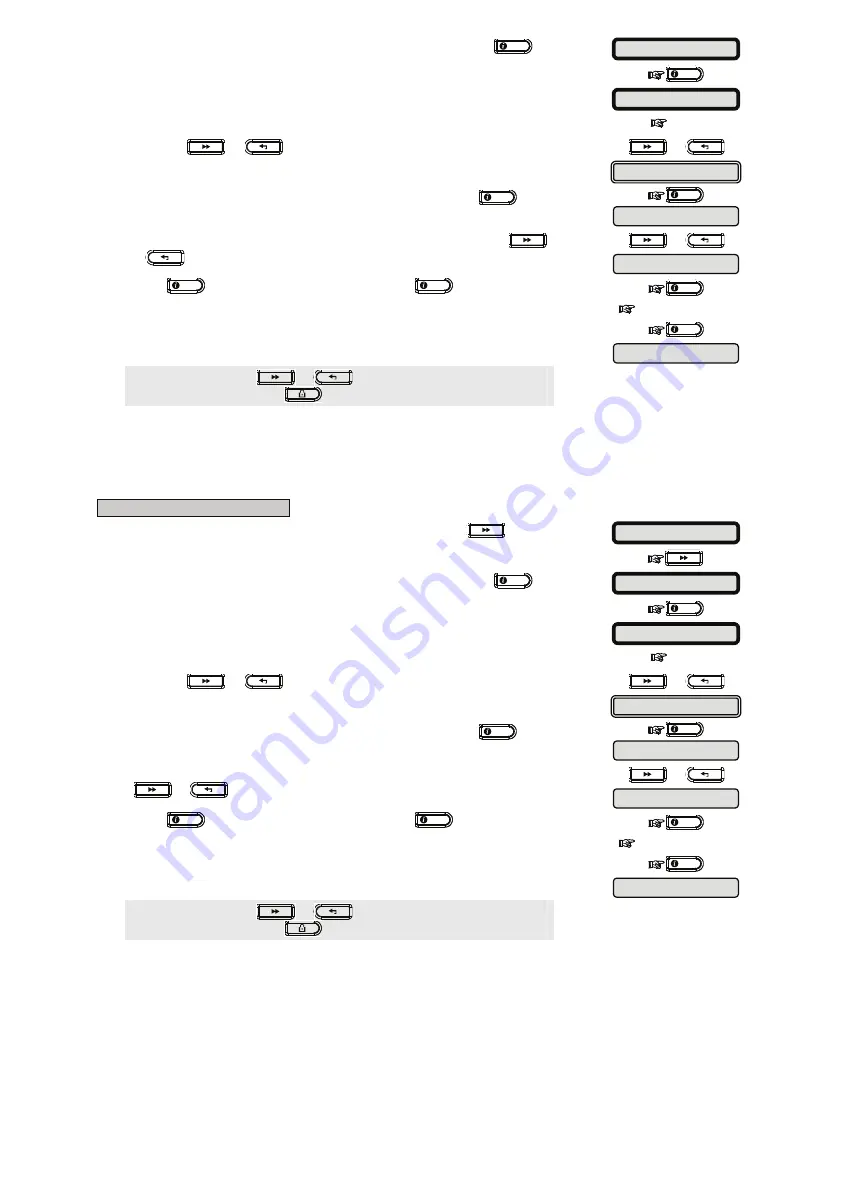
20:LATCHKEY


12:PANIC ALARM


20:LATCHKEY 

01:ENTRY DELAY 1 

ENTER CODE: 


INSTALLER MODE 

READY 00:00 

DEFINE PANEL 

12:PANIC ALARM 

01:ENTRY DELAY 1 

ENTER CODE: 


INSTALLER MODE 

DEFINE PANEL 

Summary of Contents for PowerMax10-G2

Page 1: ...PowerMax10 Fully supervised wireless alarm control system Installer Guide ...

Page 2: ...2 Configuring GPRS BB Communicators 22 4 6 3 Configuring Event Reporting to Monitoring Station 25 4 6 3 1 Configuring the Types of Events to be Reported 26 4 6 3 2 Configuring the Communicators Report Sequence 26 4 6 3 3 Configuring Account Numbers to be Reported to the Monitoring Station 27 4 6 3 4 Configuring the Monitoring Station s Telephone Numbers and IP Addresses 28 4 6 3 5 Configuring the ...

Page 3: ...upplied with 3 instruction manuals Installer Guide this manual for your exclusive use User s Guide for your use during installation only Must be handed over to the master user after testing the system Accessories Guide includes a full description of devices that are supported by the PowerMax10 G2 system Appendices A 1 and A 2 will help you prepare an installation plan Please take time to fill out ...

Page 4: ...lp by using an emergency transmitter Tracking inactivity of elderly physically handicapped and infirm people Data Retrieval Alarm memory trouble event log Real Time Clock RTC The control panel keeps and displays time and date This feature is also used for the log file by providing the date and time of each event Compliance with U S Standards USA FCC CFR 47part 15 and part 68 UL 1023 UL 985 UL 1635...

Page 5: ...shall be readily accessible c The rating of the external circuit breaker shall be 16A or less d The cables for the AC mains connection shall have an overall diameter of 13mm and 16mm conduit Please refer to Figure 3 2 Power Cable Connection 3 1 1 Inserting Backup Battery Connect battery pack as shown in the next drawing 1 2 1 Battery insertion 2 Battery connection Figure 3 1 Connecting Battery 3 1...

Page 6: ...ted to the telephone network using RJ11 connector which complies with Part 68 rules and requirements adopted by ACTA and properly installed RJ31X connector See drawing below for details In the case that RJ31X is not available consult your telephone company or a qualified installer the telephone line should be connected to the PowerMax10 G2 unit first and then all other home equipment should be con...

Page 7: ...vice is prohibited Connection to party lines service is subject to state tariffs 3 2 System Planning Programming It pays to plan ahead use the tables in appendices A and B at the end of this guide to register the intended location of each detector the holder and assignment of each transmitter Gather up all transmitters and detectors used in the system and mark each one in accordance with your depl...

Page 8: ...is disarmed 3 4 2 PowerLink Installation The PowerLink module enables viewing the PowerMax10 G2 system over the internet for further details see the PLINK PRO Installation Instructions The Broadband Module modem auto detection feature enables automatic enrollment of the Broadband Module modem into the PowerMax10 G2 control panel memory Broadband Module modem auto detection is activated in one of t...

Page 9: ...splayed 4 3 Permissions and User Codes The PowerMax10 G2 system includes four code levels as follows Installer Code By using the installer code the menu enables changing the installer code Master Installer Code By using the master installer code the menu enables changing both master installer code and installer code User Code See PowerMax10 G2 User Guide Master User Code See PowerMax10 G2 User Gui...

Page 10: ...his section Note For Control Panel that has installer code master installer code the following functions are available only if the MASTER INSTALLER code is entered PSTN GSM RCVR1 RCVR 1 ACCOUNT PSTN GSM RCVR2 RCVR 2 ACCOUNT PSTN RPRT FORMAT 4 2 PLS RATE REPORT EVENTS RPRT CNFRM ALRM SEND 2WV CODE VOICE Monitoring Station RINGBACK TIME PSTN RPRT RETRY GSM RPRT RETRY MAST DL CODE By using the master...

Page 11: ...r your installer code OK I 3 Enter your Installer Code CODE 4 Press the or button repeatedly and select the DEFINE PANEL option or 5 When the PowerMax10 G2 display reads DEFINE PANEL press OK I The PowerMax10 G2 display will read 01 ENTRY DELAY 1 OK I 6 When the PowerMax10 G2 display reads 01 ENTRY DELAY 1 press the or button repeatedly until the display will read 36 USER PERMIT or 7 Press OK I an...

Page 12: ...e system under violence or menace To initiate a duress message the user must disarm the system with the duress code 2580 by default Here you can change the code digits or enter 0000 to disable the duress feature The system does not allow the user to program the duress code saved in this memory location as an existing user code Note Duress Code is not applicable in the UK To Configure a Duress Code...

Page 13: ...re beginning gather all the devices that you intend to enroll and make sure they all have batteries installed Your control panel must recognize the unique identification code ID of each such detector in order to supervise them receive their signals and respond accordingly Before enrolling the lens at the front of PIR and dual technology sensors should be masked to prevent inadvertent transmission ...

Page 14: ...utton to move to the LOCATION menu see section 4 4 2 1 or press the button to take you to OK TO EXIT 4 4 2 1 Assigning a Location Zone type and Chime Option B To Assign a Location Zone Type and Chime Option The PowerMax10 G2 system behavior is defined according to one of 15 zone types assigned to each of the system s 30 wireless wired zones Note This step is applicable to detectors only Continue b...

Page 15: ...The PowerMax10 G2 has two types of delay zones for which different delay times may be set Entry Delay The entry delay begins once the user enters the protected area via a specific doorway his entry is sensed by a delay zone detector To avoid an alarm he must reach the keypad via interior zones which become follower zones during the entry delay and disarm the system before the delay expires When th...

Page 16: ...rnal sensor For outdoor or refrigerator installations a waterproof temperature probe optional is used There are a total of four fixed temperature points and the user can enable one or more temperature points Upon detection of change in temperature a digital message is transmitted and the event is reported 24 Hour Zones 24 hour zones are mainly used for PANIC buttons perimeter detectors and anti ta...

Page 17: ...ustom 5 4 4 3 Adding Wired Zones Required tools Cutter and slotted screwdriver 3 mm blade PowerMax10 G2 wiring is shown in Figure 4 1 CABLES ROUTING GUIDE 1 2 A B C A Cables entry options B Back unit C Cable clips To Route the Cable 1 Remove the left or right side cables entry knockout s and enter the required cable s 2 Remove and use as cable clamp s ...

Page 18: ...SORS MOTION SENSORS SMOKE SENSORS WIRED SENSORS KEYFOBS SIRENS and REPEATERS for example MOTION SENSORS or 5 Press the OK I button The PowerMax10 G2 display will read Z01 Motion Sens OK I 6 Press the or button repeatedly to select the motion sensor to be deleted for example Z03 Motion Sens or 7 Press the OK I button The PowerMax10 G2 display will read OFF to delete OK I 8 Press the button The Powe...

Page 19: ... SENSORS MOTION SENSORS SMOKE SENSORS and WIRED SENSORS for example MOTION SENSORS or 9 When the PowerMax10 G2 display reads Z01 Motion Sens press OK I The PowerMax10 G2 display will read LOCATION OK I 10 Press OK I The PowerMax10 G2 display will read Z01 LOCATION 11 When the PowerMax10 G2 display reads LOCATION press OK I OK I The PowerMax10 G2 display will read Front door 12 Press the or button ...

Page 20: ...TALLER MODE 2 When the PowerMax10 G2 display reads INSTALLER MODE press OK I The screen will now prompt you to enter your installer code OK I 3 Enter your Installer Code CODE 4 Press the or button repeatedly and select the DEFINE PANEL option or 5 When the PowerMax10 G2 display reads DEFINE PANEL press OK I The PowerMax10 G2 display will read 01 ENTRY DELAY 1 OK I 6 When the PowerMax10 G2 display ...

Page 21: ...tton repeatedly until the PowerMax10 G2 display reads INSTALLER MODE 2 When the PowerMax10 G2 display reads INSTALLER MODE press OK I The screen will now prompt you to enter your installer code OK I 3 Enter your Installer Code CODE 4 Press the or button repeatedly and select the DEFINE PANEL option or 5 When the PowerMax10 G2 display reads DEFINE PANEL press OK I The PowerMax10 G2 display will rea...

Page 22: ...vent Reporting Configuration 4 6 1 General The PowerMax10 G2 system uses an IP platform that supports GSM and GPRS cellular communication and broadband to forward all events received at the control panel to the monitoring station 4 6 2 Setup Report Communicators 4 6 2 1 Configuring PSTN GSM Communicators 1 Make sure the system is disarmed and then press the button repeatedly until the PowerMax10 G...

Page 23: ...Press the or button to select between disable and every 28 days for example every 28 days or 19 Press OK I to confirm the selection The PowerMax10 G2 display will revert to GSM KEEP ALIVE OK I You can now press the button to revert to the AREA CODE menu or press the button to take you to OK TO EXIT 4 6 2 2 Configuring GPRS BB Communicators The GSM GPRS module is capable of communicating with the M...

Page 24: ...ress the button The PowerMax10 G2 display will read GSM REPORT Here you determine whether the alarm system will report events to the Monitoring Station via the GSM Voice channel 31 When the PowerMax10 G2 display reads GSM REPORT press OK I The PowerMax10 G2 display will read disable OK I 32 Press the or button to select between disable and enable for example enable or 33 Press OK I to confirm the ...

Page 25: ... 46 Press OK I to confirm The PowerMax10 G2 display will revert to GPRS PASSWORD OK I 47 Press the button The PowerMax10 G2 display will read PIN CODE 48 Enter the PIN code of the SIM card installed in the PowerMax10 G2 unit up to 16 digits PIN CODE 49 Press OK I to confirm The PowerMax10 G2 display will revert to PIN CODE OK I 50 Press the button The PowerMax10 G2 display will read FORCE HOME NTW...

Page 26: ...ts 4 6 3 Configuring Event Reporting to Monitoring Station Here you determine which types of event will be reported to Monitoring Stations Due to lack of space in the display abbreviations are used alarm is alrm alert is alrt and open close is o c The asterisk J is a separator between events reported to Monitoring Station 1 and events reported to Monitoring Station 2 Messages are divided by type i...

Page 27: ... c o c all alrt alrt alrm all alrm disable report and all backup for example all backup or 10 Press OK I to confirm the selection The PowerMax10 G2 display will revert to REPORT EVENTS OK I You can now press the button to take you to the 1st RPRT METHOD menu or press the button to take you to OK TO EXIT 4 6 3 2 Configuring the Communicators Report Sequence Continue below from the previous section ...

Page 28: ...able cellular broadband and PSTN for example PSTN or 22 Press OK I to confirm the selection The PowerMax10 G2 display will revert to 3rd RPRT METHOD OK I 23 Press the button The PowerMax10 G2 display will read DUAL REPORTING Here you determine whether to report events using PSTN and cellular at the same time instead of waiting for the 1st method to fail before trying the 2nd method 24 When the Pow...

Page 29: ...rameters to the local requirements Continue below from the previous section or repeat steps 1 to 7 of section 4 6 3 1and then press the or button repeatedly until the PowerMax10 G2 display will read PSTN GSM RCVR1 35 Press the button The PowerMax10 G2 display will read PSTN GSM RCVR1 Here you program telephone number of the 1st Monitoring Station including area code 16 digit max to which the syste...

Page 30: ... 1 OK I 55 Press the button The PowerMax10 G2 display will read SMS RCVR2 Here you enter the telephone number of the SMS receiver that is located in the 2nd Monitoring Station 56 When the PowerMax10 G2 display reads SMS RCVR2 press the OK I button OK I 57 Enter the telephone number of the second SMS receiver see table at the end of this section for further details 58 Press the OK I button The Powe...

Page 31: ...I 63 Press the button The PowerMax10 G2 display will read 4 2 PULSE RATE Here you select the pulse rate at which data will be sent to Monitoring Stations if any one of the 4 2 formats has been selected in PSTN Report Format 64 When the PowerMax10 G2 display reads 4 2 PULSE RATE press the OK I button The PowerMax10 G2 display will read 20 pps OK I 65 Press the or button repeatedly to select between...

Page 32: ...le communication to the Monitoring Station 76 When the PowerMax10 G2 display reads LAN RPRT RETRY press the OK I button The PowerMax10 G2 display will read 4 attempts OK I 77 Press the or button repeatedly to select between 2 attempts 4 attempts 8 attempts 12 attempts and 16 attempts for example 12 attempts or 78 Press OK I to confirm the selection The PowerMax10 G2 display will revert to LAN RPRT...

Page 33: ... the telephone line is disconnected the event tel line fail will be stored in the event log OK I 89 When the PowerMax10 G2 display reads PSTN press the OK I button The PowerMax10 G2 display will read immediately OK I 90 Press the or button repeatedly to select between immediately 5 minutes 30 minutes 60 minutes 180 minutes and don t report for example 60 minutes or 91 Press OK I to confirm the sel...

Page 34: ...y will read AUTO TEST TIME 101 Press the button The PowerMax10 G2 display will read RPRT CNFRM ALARM Here you determine whether the system will report whenever 2 or more events confirmed alarm occur during a specific period 102 Press the OK I button The PowerMax10 G2 display will read disable report OK I 103 Press the or button repeatedly to select between disable report enable bypass and enable r...

Page 35: ...G2 display will revert to SYS INACT REPORT OK I You can now press the button to take you to the REPORT EVENTS menu see section 4 6 2 1 or press the button to take you to OK TO EXIT 4 6 4 Configuring Event Reporting to Users A To Enable Report to Users 1 Make sure the system is disarmed and then press the button repeatedly until the PowerMax10 G2 display reads INSTALLER MODE 2 When the PowerMax10 G...

Page 36: ...REPORT TO PRVT OK I You can now press the button to take you to the VOICE REPORT menu see the next section or press the button to take you to OK TO EXIT C To Configure Event Types to be Reported to User 11 Press the button The PowerMax10 G2 display will read VOICE REPORT 12 When the PowerMax10 G2 display reads VOICE REPORT press the OK I button The PowerMax10 G2 display will read 1st private tel O...

Page 37: ...on A maximum of 2 dialing attempts is permitted by the Australian Telecommunication Authority or 27 Press OK I to confirm the selection The PowerMax10 G2 display will revert to Redial attempts OK I 28 Press the button The PowerMax10 G2 display will read Tel acknowledge Here you determine whether the system will use the single acknowledge or the all acknowledge mode when reporting to private teleph...

Page 38: ...igits maximum to which pre selected event types will be reported OK I 3rd SMS TEL NO 43 Press the OK I button The PowerMax10 G2 display will revert to 3rd SMS tel OK I 44 Press the button The PowerMax10 G2 display will read 4th SMS tel 45 Press the OK I button and enter the fourth SMS phone number including area code 16 digits maximum to which pre selected event types will be reported OK I 4th SMS...

Page 39: ... the number of times each zone is allowed to initiate an alarm within a single arming disarming period including tamper power failure events of detectors PowerMax10 G2 wireless siren etc If the alarms number from a specific zone exceeds the programmed number the control panel automatically bypasses the zone to prevent recurrent siren noise and nuisance reporting to the Monitoring Station The zone ...

Page 40: ...OK I 6 When the PowerMax10 G2 display reads 01 ENTRY DELAY 1 press the or button repeatedly until the display will read 21 NOT ACTIVE or 7 Press OK I and make the selection and then press OK I to confirm The PowerMax10 G2 display will revert to 21 NOT ACTIVE OK I SELECT OPTION OK I You can now press the or button to program any other menu in DEFINE PANEL or press the button to take you to OK TO EX...

Page 41: ...will now prompt you to enter your installer code OK I 3 Enter your Installer Code CODE 4 Press the or button repeatedly and select the DEFINE PANEL option or 5 When the PowerMax10 G2 display reads DEFINE PANEL press OK I The PowerMax10 G2 display will read 01 ENTRY DELAY 1 OK I 6 When the PowerMax10 G2 display reads 01 ENTRY DELAY 1 press the or button repeatedly until the display will read 34 AC ...

Page 42: ... PANEL or press the button to take you to OK TO EXIT 4 7 7 Configuring a Confirmed Alarm Here you determine that if 2 successive alarms will occur during a specific period the second alarm will be considered as a confirmed alarm for confirmed alarm reporting see par 4 6 3 2 Configuring the Event Types to be Reported Options disable default in USA 30 min 45 min 60 min default or 90 min To Configure...

Page 43: ...the PowerMax10 G2 display reads DEFINE PANEL press OK I The PowerMax10 G2 display will read 01 ENTRY DELAY 1 OK I 6 When the PowerMax10 G2 display reads 01 ENTRY DELAY 1 press the or button repeatedly until the display will read 30 BELL REP OPT or 7 Press OK I and make the selection and then press OK I to confirm The PowerMax10 G2 display will revert to 30 BELL REP OPT OK I SELECT OPTION OK I You ...

Page 44: ...ther a Missing Device Causes the System to Become NOT READY Here you determine if the system will be in NOT READY status when there is a supervision failure In the in supervision mode the system will be in NOT READY status if during the last 20 minutes a supervision message was not received Options normal default and in supervision Note To comply with EN requirements in supervision must be selecte...

Page 45: ...en the PowerMax10 G2 display reads 01 ENTRY DELAY 1 press the or button repeatedly until the display will read 15 SUPERVISION or 7 Press OK I and make the selection and then press OK I to confirm The PowerMax10 G2 display will revert to 15 SUPERVISION OK I SELECT OPTION OK I You can now press the or button to program any other menu in DEFINE PANEL or press the button to take you to OK TO EXIT 4 8 ...

Page 46: ...elays Available options for each delay are 00s 15s default for entry delay 2 30s default for entry delay 1 45s 60s 3m and 4m Note To comply with CP 01 requirements 00s and 15s options are not available Note To comply with EN requirements the entry delay must not exceed 45 sec Note To comply with UL requirements the entry delay must not exceed 15 sec To Configure the Duration of the Entry Delays 1 ...

Page 47: ... 1 press the or button repeatedly until the display will read 03 EXIT DELAY or 7 Press OK I and make the selection and then press OK I to confirm The PowerMax10 G2 display will revert to 03 BELL REP OPT OK I SELECT OPTION OK I You can now press the or button to program any other menu in DEFINE PANEL or press the button to take you to OK TO EXIT 4 8 4 Enabling Quick Arm Here you determine whether t...

Page 48: ...splay reads INSTALLER MODE press OK I The screen will now prompt you to enter your installer code OK I 3 Enter your Installer Code CODE 4 Press the or button repeatedly and select the DEFINE PANEL option or 5 When the PowerMax10 G2 display reads DEFINE PANEL press OK I The PowerMax10 G2 display will read 01 ENTRY DELAY 1 OK I 6 When the PowerMax10 G2 display reads 01 ENTRY DELAY 1 press the or but...

Page 49: ... 8 This mode is useful when parents at work want to be informed of a child s return from school The options are Latchkey ON and Latchkey OFF default To Enable Latchkey Arming 1 Make sure the system is disarmed and then press the button repeatedly until the PowerMax10 G2 display reads INSTALLER MODE 2 When the PowerMax10 G2 display reads INSTALLER MODE press OK I The screen will now prompt you to e...

Page 50: ...ake the selection and then press OK I to confirm The PowerMax10 G2 display will revert to 11 TROUBLE BEEPS OK I SELECT OPTION OK I You can now press the or button to program any other menu in DEFINE PANEL or press the button to take you to OK TO EXIT 4 9 2 Enabling Piezo Beeps Here you determine whether warning beeps will sound or muted during exit and entry delays An additional option is to mute ...

Page 51: ...ess OK I The PowerMax10 G2 display will read 01 ENTRY DELAY 1 OK I 6 When the PowerMax10 G2 display reads 01 ENTRY DELAY 1 click the or buttons repeatedly until the display will read 22 BACK LIGHT or 7 Press OK I and make the selection and then press OK I to confirm The PowerMax10 G2 display will revert to 22 BACK LIGHT OK I SELECT OPTION OK I You can now press the or button to program any other m...

Page 52: ... Fire and Emergency will cause normal display return and the second press will perform the key function Regarding the Fire and Emergency keys the first key press will cause normal display return and also will perform the Fire Emergency function Options scrn saver OFF default refresh by code refresh by key Note To comply with EN requirements refresh by code must be selected To Configure the Screen ...

Page 53: ...ION OK I You can now press the or button to program any other menu in DEFINE PANEL or press the button to take you to OK TO EXIT 4 9 7 Enabling Keyfob Low Battery Acknowledgement Here you determine whether the user will hear or will not hear low battery sound when he tries to disarm the system with a keyfob whose battery voltage is low Available options are keyfob L B on the user has to acknowledg...

Page 54: ... press the or button repeatedly until the PowerMax10 G2 display will read DEFINE CUSTOM or 5 Press the OK I button The PowerMax10 G2 display will read CUST ZONES NAME OK I 6 When the PowerMax10 G2 display reads CUST ZONES NAME press the OK I button OK I The PowerMax10 G2 display will read EDIT USER TERM 1 7 Press the OK I button The PowerMax10 G2 display will read Custom 1 OK I Note The table at t...

Page 55: ...will be turned on upon event occurrence in these zones and will be turned off upon next event occurrence alternately LINE FAIL PGM output is ON if telephone line is disconnected For PGM devices you can select the following actions FLASH ON ALARM you can select no flash or all light flash to control PGM lighting devices in alarm conditions LOCKOUT TIME you can enter daytime limits between which PGM...

Page 56: ...ill read PGM BY ARM HOME 15 When the PowerMax10 G2 display reads PGM BY ARM HOME press the OK I button OK I The PowerMax10 G2 display will read disable 16 Press the or button repeatedly to select between disable turn ON turn OFF and pulse active for example pulse active or 17 Press OK I to confirm the selection The PowerMax10 G2 display will revert to PGM BY ARM HOME OK I 18 Press the button The P...

Page 57: ...ax10 G2 display will read PGM BY KEYFOB 31 When the PowerMax10 G2 display reads PGM BY KEYFOB press the OK I button OK I The PowerMax10 G2 display will read disable 32 Press the or button repeatedly to select between disable turn ON turn OFF pulse active and toggle for example toggle OK I 33 Press OK I to confirm the selection The PowerMax10 G2 display will revert to PGM BY KEYFOB OK I 34 Press th...

Page 58: ... G2 display will read by line fail NO 49 Press the or button to select between by line fail NO and by line failYES for example by line failYES OK I 50 Press OK I to confirm the selection The PowerMax10 G2 display will revert to PGM BY LINE FAIL OK I Clicking the or buttons at any stage in the procedure will take you to OK TO EXIT B To Configure PGM Lighting Devices in Alarm Conditions and To Set D...

Page 59: ... AM and PM are selected by pressing and respectively 16 Press the OK I button The PowerMax10 G2 display will revert to stop HH MM OK I Pressing the or buttons at any stage in the procedure will take you to OK TO EXIT 4 12 Programming User Settings This mode provides you with a gateway to the user functions through the regular user programming menu To Set User Codes 1 Make sure the system is disarm...

Page 60: ...de OK I 3 Enter your Installer Code CODE 4 Press the or button repeatedly until the PowerMax10 G2 display reads DEFINE COMM option or 5 When the PowerMax10 G2 display reads DEFINE COMM press OK I The PowerMax10 G2 display will read 1 PSTN GSM OK I 6 When the PowerMax10 G2 display reads 1 PSTN GSM press the or button repeatedly until the display will read 3 Monitoring Station REPORTING or 7 Press O...

Page 61: ...l revert to Inst downl code OK I OK I 21 Press the button The PowerMax10 G2 display will read Upload option Here you determine whether the PowerMax10 G2 data can be uploaded into a computer while the system is in disarm state or at any time in HOME AWAY arming disarm state 22 When the PowerMax10 G2 display reads Upload option press the OK I button The PowerMax10 G2 display will read any time OK I ...

Page 62: ... telephone number When the PowerMax10 G2 responds to an incoming call from the telephone number defined here it creates a connection to that IPMP for uploading downloading data 40 When the PowerMax10 G2 display reads 2nd caller ID press the OK I button OK I 41 Enter the second IP receiver telephone number 42 Press the OK I button twice The PowerMax10 G2 display will revert to 2nd caller ID OK I OK...

Page 63: ...now perform automatic testing of all enrolled devices in the following order repeaters sirens detectors keypads The PowerMax10 G2 system will perform automatic testing of keyfobs if enrolled at the end of testing all other devices Note Zxx indicates the type of device and device number that is being tested NNN indicates the number of devices that have not yet been tested At this stage if any key i...

Page 64: ... TEST ALL DEVICES press the and buttons repeatedly until the PowerMax10 G2 display will read SHOW ALL DEVICES or 3 When the PowerMax10 G2 display reads SHOW ALL DEVICES press the OK I button The PowerMax10 G2 display switches between the average signal strength indication for the last 24 hours and between the current signal strength indications of the first device type OK I 4 Press the button to v...

Page 65: ... repeatedly until the PowerMax10 G2 display reads INSTALLER MODE 2 When the PowerMax10 G2 display reads INSTALLER MODE press OK I OK I The screen will now prompt you to enter your installer code 3 Enter your Installer Code The PowerMax10 G2 display will read NEW INSTL CODE CODE 4 When the PowerMax10 G2 display reads NEW INSTL CODE press the or button repeatedly until the PowerMax10 G2 display will...

Page 66: ...and Module is not registered to the PowerMax10 G2 the menu LAN CONNECT TEST will not be displayed 1 Make sure the system is disarmed and then press the button repeatedly until the PowerMax10 G2 display reads INSTALLER MODE 2 When the PowerMax10 G2 display reads INSTALLER MODE press OK I OK I The screen will now prompt you to enter your installer code 3 Enter your Installer Code The PowerMax10 G2 d...

Page 67: ...to test result within 70 sec Invalid result Broadband Module responds with a result code that is not recognized by the PowerMax10 G2 5 1 7 LAN Reset Option 1 Make sure the system is disarmed and then press the button repeatedly until the PowerMax10 G2 display reads INSTALLER MODE 2 When the PowerMax10 G2 display reads INSTALLER MODE press OK I OK I The screen will now prompt you to enter your inst...

Page 68: ...telephone number was already defined see section 4 6 3 2 Configuring the Event Types to be Reported the PowerMax10 G2 display will read COMMUNICATING which is displayed during the dialing process If the UL DL server telephone number was not defined see section 4 6 3 2 Configuring the Event Types to be Reported the PowerMax10 G2 display will read TEL NOT DEFINED which is displayed for approx 30 sec...

Page 69: ... is detected Locate the source of interference by switching off any wireless devices cordless telephones wireless ear plugs etc in the house for 2 minutes then check if trouble continues Use also RF diagnostics to check signal strength The battery in a sensor keyfob or wireless commander is near the end of its useful life i For AC powered devices check AC power is available and connected to the de...

Page 70: ...the battery compartment lid Clear it by arming the system and immediately disarming 7 4 Fuse Replacement The PowerMax10 G2 has an internal fuse that has automatic reset Therefore there is no need to replace the fuse When over current condition occurs the fuse cuts off the circuit current Upon fault current being removed for several seconds the fuse is automatically reset and allows current flow th...

Page 71: ...When the PowerMax10 G2 display reads NEW INSTL CODE press the or button repeatedly until the PowerMax10 G2 display will read SERIAL NUMBER or 5 When the PowerMax10 G2 display reads SERIAL NUMBER press the OK I button OK I 6 The PowerMax10 G2 display will read the serial number SERIAL NUMBER 7 Press the button The display will read the version of the PowerMax10 G2 unit UNIT VERSION Pressing the or ...

Page 72: ...ill change to CLEAR EVENT LOG 3 Press the OK I button The display will change to OFF to delete OK I 4 Press the button The display will change to OK TO EXIT At this stage in the procedure pressing the or buttons will take you to OK TO EXIT without erasing the event log Pressing the button will return you to CLEAR EVENT LOG 5 Press the OK I button OK I The system erases the event log and reverts to...

Page 73: ...ation for each detector When programming you may select one of 26 available locations plus 5 custom locations that you can add see Zones Devices menu Zones 29 only is hardwired zones A2 Keyfob Transmitter List Transmitter Data AUX button Assignments No Type Holder Skip exit delay or Arming instant 1 2 3 4 5 Indicate the desired function if any 6 Skip exit delay F 7 Arming instant F 8 A3 Emergency ...

Page 74: ...R Recent Close TR Tamper Restore EA Door Open WA Flood alarm FA Fire Alarm WR Flood alarm restore FT Fire Detector Clean XR Sensor Battery Restore FJ Fire detector trouble XT Sensor Battery Trouble FR Fire Restore YR System Battery Restore GA Gas alarm YT System Battery Trouble Disconnection GR Gas alarm restore YX Service Required GT Gas trouble B3 4 2 Event Codes Note The report to Monitoring St...

Page 75: ...initiated the internal sounder is activated first for a limited period of time which is the abort period set by the installer If you cause an alarm accidentally you can disarm the system within the abort period before the real sirens start and before the alarm is reported to the remote responders Alarm There are 2 kinds of alarm Loud alarm both internal and external sirens blare out constantly and...

Page 76: ...ransmits its unique identification code accompanied by an alarm signal and various other status signals to the control panel The control panel if not armed at that time will consider the alarm system as not ready for arming until it receives a restored signal from the same detector Motion Detector Wireless A passive Infrared motion sensor and a wireless PowerG transmitter in a shared housing Upon ...

Page 77: ...LY ARISING FROM PURCHASER S USE OR INABILITY TO USE THE PRODUCT OR FOR LOSS OR DESTRUCTION OF OTHER PROPERTY OR FROM ANY OTHER CAUSE EVEN IF MANUFACTURER HAS BEEN ADVISED OF THE POSSIBILITY OF SUCH DAMAGE THE MANUFACTURER SHALL HAVE NO LIABILITY FOR ANY DEATH PERSONAL AND OR BODILY INJURY AND OR DAMAGE TO PROPERTY OR OTHER LOSS WHETHER DIRECT INDIRECT INCIDENTAL CONSEQUENTIAL OR OTHERWISE BASED ON...

Page 78: ...eless alarm control system Fully supervised wireless alarm control stem Fully supervised wireless alarm control system Fully supervised wireless alarm ntrol system Fully supervised wireless alarm control system Fully supervised wireless arm control system Fully supervised wireless alarm control system Fully supervised reless alarm control system Fully supervised wireless alarm control system Fully...

Reviews: