Installation Drawings
Vertiv
|
Large System, 3-Phase UPS Battery System Installation Manual
45
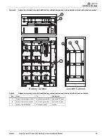
Figure 43
Liebert NXL
™
terminal details UPS 625/750kVA to front-terminal battery and attached junction cabinet
point-to-point wiring
Table 11
Liebert NXL terminal details UPS 625/750kVA to front-terminal battery and attached junction cabinet
point-to-point Interconnect wiring
Run
From
To
Conductors
A1
Battery Cabinet Negative Bus
Junction Negative Bus
Negative DC Power (LH Mount)
B1
Battery Cabinet Positive Bus
Junction Positive Bus
Positive DC Power (LH Mount)
A2
Battery Cabinet Negative Bus
Junction Negative Bus
Negative DC Power (RH Mount)
B2
Battery Cabinet Positive Bus
Junction Positive Bus
Positive DC Power (RH Mount)
D
Junction Positive Bus
UPS Cabinet Positive Bus
Positive DC Power
E
Junction Negative Bus
UPS Cabinet Negative Bus
Negative DC Power
F
Junction Ground
UPS Cabinet Ground
Ground
G
Battery Cabinet Battery
Interface Board (BIB)
UPS External Interface Board (EIB)
CAN Control Cables
ATTACHED JUNCTION
CABINET RIGHT SIDE
UPS LEFT SIDE
Rectifier (Part A)
UPS LEFT FRONT
(Part A)
BATTERY CABINET
1. All power and control wiring between
battery cabinet and junction cabinet
is supplied.
2. All power wiring between junction
cabinet and UPS is supplied by others.
3. All control wiring between battery
cabinet and UPS is supplied by others.
TOP VIEW
B
A
E
D
F
Ground Bus
DC Input
C
B
A
DC (+)
Input
DC (-)
Input
E
D
F
G
A1 & B1
LH Mount
A2 & B2
RH Mount
G
C
B1
A1
B2
A2
Summary of Contents for Liebert NXL 1100
Page 2: ...Liebert Large System 3 Phase UPS Battery System Installation Manual...
Page 69: ...Specifications Vertiv Large System 3 Phase UPS Battery System Installation Manual 62 NOTES...
Page 70: ...Specifications Vertiv Large System 3 Phase UPS Battery System Installation Manual 63...
Page 71: ...Specifications Vertiv Large System 3 Phase UPS Battery System Installation Manual 64...


