background image

12

Slide the top drawer into the shelf.

13

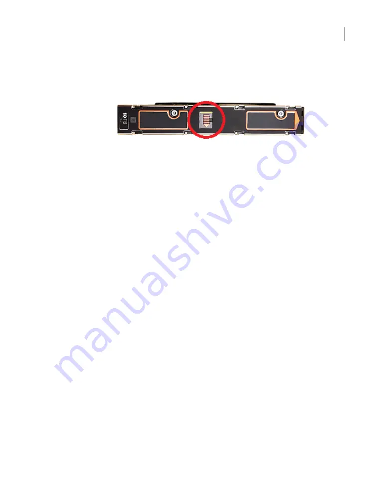
If you need to remove a disk drive, slide the release latch to the right. The disk
pops up.

14

Engage the anti-tamper locks as needed.

Installing the compute node rack rails

Veritas recommends the following.

The compute node requires two RUs of space. Install the node in the space that
is directly above the storage shelves.

Always install the heavier storage shelves at the bottom of the rack. Best
practices recommend that you install hardware at the bottom of a rack first. Then
work your way up the rack.

Two people should install the rails; one person at the back of the rack and one
at the front.

41

Hardware installation procedures

Installing the compute node rack rails

Summary of Contents for Access 3340

Page 1: ...Veritas Access 3340 Appliance Hardware Installation Guide ...

Page 2: ...itten authorization of Veritas Technologies LLC and its licensors if any THE DOCUMENTATION IS PROVIDED AS IS AND ALL EXPRESS OR IMPLIED CONDITIONS REPRESENTATIONS AND WARRANTIES INCLUDING ANY IMPLIED WARRANTY OF MERCHANTABILITY FITNESS FOR A PARTICULAR PURPOSE OR NON INFRINGEMENT ARE DISCLAIMED EXCEPT TO THE EXTENT THAT SUCH DISCLAIMERS ARE HELD TO BE LEGALLY INVALID VERITAS TECHNOLOGIES LLC SHALL...

Page 3: ...page 2 The latest documentation is available on the Veritas website https sort veritas com documents Documentation feedback Your feedback is important to us Suggest improvements or report errors or omissions to the documentation Include the document title document version chapter title and section title of the text on which you are reporting Send feedback to APPL docs veritas com You can also see ...

Page 4: ...ute node shipping container contents 19 Dimensions and determining rack locations 19 Best practices for rack installation 23 Heat dissipation guidelines 24 Cable length verification 25 Prerequisites for IPMI configuration 25 Chapter 3 Hardware installation procedures 27 Overview 27 Installing a storage shelf 28 Installing disk drives into a storage shelf 38 Installing the compute node rack rails 4...

Page 5: ...ppendix A Configuring the disk space after adding one or more new Expansion Storage Shelves 76 Adding the disk space of an Expansion Storage Shelf from the Access 3340 Appliance shell menu 76 5 Contents ...

Page 6: ... storage shelf Expansion module Cables and connectors Access 3340 compute node and 5U84 storage shelves The Veritas 5U84 storage shelves provide storage capacity to the two Access 3340 compute nodes You must have a Primary Storage Shelf that connects to the compute nodes You can use up to three optional Expansion Storage Shelves for additional storage With the required 5U84 Primary Storage Shelf t...

Page 7: ... the Primary shelf to the compute nodes Each module has a SAS3 Expansion port for connection to Expansion Storage Shelves The Expansion shelves contain two I O modules for connectivity to the Primary shelf and to other Expansion shelves Refer to the Veritas Access 3340 Appliance Product Description at the following site for details about usable storage capacity Appliance documentation Access 3340 ...

Page 8: ...iption Component Number The System Status LED uses the colors green and amber to display the health of the compute node Power button with integrated LED 1 The drive activity LED on the front panel indicates drive activity from the on board hard disk controllers Hard Drive Activity LED 2 The System ID button toggles on the integrated ID LED and the blue server board LED and off The system ID LED id...

Page 9: ...ics for a given issue where a memory dump is necessary to help determine the cause of the problem To prevent an inadvertent system halt the NMI button is located behind the front control panel faceplate It is only accessible with the use of a small tipped tool NMI button recessed a tool is required for use 7 The System Status LED is bi color indicator that uses the colors green and amber to displa...

Page 10: ...ontains a SAS3 HBA card that connects to the SAS3 ports on the Primary Storage Shelf 6 Riser Assembly 2 Slot 1 contains a SAS3 HBA card that connects to the SAS3 ports on the Primary Storage Shelf 7 One two port 10GbE network interface card NIC From left to right the ports are NIC5 eth4 and NIC6 eth5 The following diagram shows the location of the Ethernet ports from 0 to 5 Note The embedded Ether...

Page 11: ...e top drawer contains slots 0 through 41 The bottom drawer contains slots 42 through 83 The following diagrams show all of the slots in each drawer The photographs show the number of the first slot in each drawer In the top drawer slot 41 contains a blank carrier instead of a carrier with a disk drive The blank carrier is shown in blue Top drawer rear Top drawer front In the bottom drawer slot 83 ...

Page 12: ...t move disk drives to new locations Each disk drive is encased in a carrier A label at the top front end of the carrier identifies the storage capacity of the disk that is inside the carrier Carriers that contain blanks are labelled BLANK 5U84 storage shelf control panel The following table explains the components in the storage shelf control panel 12 Overview 5U84 storage shelf control panel ...

Page 13: ... fault An LED may be lit on a power supply drawer disk carrier cooling module or I O module to identify which component is at fault Module fault LED 4 Shows a change of status or a fault Typically these changes of status or faults are associated with the shelf s disk drives However the Logical Status LED can also indicate an issue with an internal RAID controller or external RAID controller or wit...

Page 14: ...efer to the following sections for information about the I O modules See 5U84 storage shelf Expansion module on page 15 5U84 storage shelf RAID controller The Primary Storage Shelf contains two RAID controllers in I O module slots The controllers are labeled A and B from left to right as you look at the rear panel of a shelf Each controller has two sets of SAS3 ports From left to right the SAS3 po...

Page 15: ...echnical Support The SAS3 ports connect to the SAS port on each RAID controller on the Primary Shelf and to other Expansion Shelves SAS3 ports Ethernet port A B C Cables and connectors Compute nodes connect to each other with 1G Ethernet cables The compute nodes connect to the Primary Storage Shelf with SAS3 cables The Primary Storage Shelf connects to Expansion Storage Shelf I O modules with SAS3...

Page 16: ...A security tie assures continued connection between the power cable and the storage shelf 16 Overview Cables and connectors ...

Page 17: ...on Prerequisites for IPMI configuration Customer provided environment and supplies The storage shelf rails can extend from 713mm 28 07in to 884mm 33 23in in length Be sure that your racks accommodate these rails For best ventilation the rack cabinet Should be at least 100 cm 4 feet from walls Should be at least 100 cm 4 feet from other cabinets on the front and back of the compute node and the sto...

Page 18: ...t for the storage shelves Refer to the following section for more details See Heat dissipation guidelines on page 24 Storage shelf shipping container contents Each storage shelf container includes other boxes and contents as follows Open Me First envelope containing Deployment plan that provides basic information and links to detailed information Cable straps Envelope containing Warranty agreement...

Page 19: ...ute node at the factory The following items ship within the compute node box Open Me First envelope containing Deployment plan that provides basic information and links to detailed information Cable straps Envelope containing Warranty agreement Environmental compliance statement USB drive with factory image Hardware such as Hardware cable connections poster Rack templates Rack rails and mounting h...

Page 20: ...ge shelf is longer than a standard IEC compliant rack Be sure that your rack cabinet and Power Distribution Units accommodate the length of the storage shelves The storage shelf rails measure 71 3cm to 88 4cm 28 to 34 8 in length Be sure that your rack accommodates this distance from the inside of the front post to the inside of the rear post Plan for additional space to accommodate power strips p...

Page 21: ...to ensure that the rails are installed straight and level One RU has three holes The holes for one RU are typically marked with a line below the bottom hole and another line at the top hole Use the rack templates to determine the mounting locations for all devices To determine rack locations for the hardware 1 Determine the total number of rack units RUs that you need as follows 21 Pre installatio...

Page 22: ...determine RU locations 3 Fold the compute node templates at the horizontal yellow lines 4 Use the following graphics to determine where pins and screws for the storage shelves fit into the rack The front of each rail includes four pins that insert into the rear of the front rack post One screw fits into the middle hole of the middle RU 22 Pre installation requirements Dimensions and determining ra...

Page 23: ...d the rack positions to help you locate them easily when mounting the hardware Best practices for rack installation Prepare for the hardware installation by following these recommendations The storage shelves are heavier than the compute node and should be installed as close to the bottom of the rack as possible Determine device order and cabling limits 23 Pre installation requirements Best practi...

Page 24: ...elves Note Data centers with two foot spaces in the front and in the back of the compute nodes are acceptable with proper cooling and ventilation The following requirements ensure sufficient cooling to the devices Veritas requires that you install the devices in a National Engineering Manufacturer s Association NEMA certified or equivalent rack Note The 5U84 storage shelf is as long as a standard ...

Page 25: ...red separately The 2 meter cable is long enough to connect the Primary Storage Shelf to the third Expansion Storage Shelf when you use the recommended configuration Note If you must have Expansion shelves in different racks be sure that the SAS3 cables are long enough Do not stretch the cables too tightly or try to use adapters or extensions Prerequisites for IPMI configuration Verify the followin...

Page 26: ... 7578 SSL 7582 Note If you have a private internal network remember to configure the settings accordingly in your network address translation NAT The remote management port must be configured as a DHCP or static address 26 Pre installation requirements Prerequisites for IPMI configuration ...

Page 27: ...ecting the hardware to two nodes Connecting to the network Connecting the power cords to the hardware Turning on the hardware and verifying operation Configuring the IPMI port from the Access Appliance shell menu Accessing and using the Veritas Remote Management interface Overview This chapter describes the procedures to install two Access 3340 compute nodes one 5U84 Primary Shelf and up to three ...

Page 28: ...sk drives weighs up to 61 65kg 135 72lbs To avoid potential equipment damage and personal injury do not install disk drives into the storage shelves before mounting them into the rack The added weight of the disk drives hinders the ability to safely install the storage shelves Use the lifting straps that are provided with the shelf to remove the shelf from the shipping container Use a mechanical l...

Page 29: ... length 3 Identify the left and the right rails which are labeled LH left hand or RH right hand on the front inside of the rail Note the ledge at the bottom of each rail The storage shelf sits on the ledges which must be positioned on the inside of the rack The ledges must not be located between the rail and the rack wall 4 Locate the pins on the front and the rear of the rails 29 Hardware install...

Page 30: ... with the hardware One side of the template shows the front of the rail The other side of the template shows the rear of the rail The template shows the five rack units RUs to scale 30 Hardware installation procedures Installing a storage shelf ...

Page 31: ...6 Start with the left rail Place the rail pins inside the front of the rack 31 Hardware installation procedures Installing a storage shelf ...

Page 32: ...ly seated in the holes in the rack posts 9 Secure the four adjuster screws as needed Do not over torque 10 Repeat the process for the right rail 11 Verify that the left rails and the right rails use the same rack holes and are parallel 32 Hardware installation procedures Installing a storage shelf ...

Page 33: ...stening screw with two washers for use after shelf is installed in rails Install the washer with the gap first 1 Front Center hole Rear Top and bottom holes Front Center hole of third rack unit RU Rear Center holes in first and fifth rack units RUs Medium sized clamping screw 2 Front N A Rear Connects from chassis lock tab to hole in triangular end of rail Front N A Rear N A Small rear fastening s...

Page 34: ...e clamping screw in the center hole of the center RU The rear of the rail requires two clamping screws Insert these screws in the middle hole in the first and the fifth RU 14 Remove any plastic film from the front and sides of the shelf Do not remove the front plate or bezel from either drawer 34 Hardware installation procedures Installing a storage shelf ...

Page 35: ... the straps in case you need to move the shelf later Warning The back end of the storage shelf is heavier than the front end From the front of the rack carefully lower the storage shelf onto the rail ledges in the rack 17 Push the shelf into the back of the rack 18 On the front of the rack use a long screw and two washers in the top and the bottom holes Place the washer with a gap onto the screw f...

Page 36: ...19 Locate the lock tabs on the left and right rear corners of the storage shelf chassis 36 Hardware installation procedures Installing a storage shelf ...

Page 37: ...he rail Secure the screw 21 On the front of the storage shelf reattach the left and the right hub caps The left cap contains the control panel The right cap contains spaces for two latches which connect to the storage shelf 37 Hardware installation procedures Installing a storage shelf ...

Page 38: ... second person installs the disks Both people can press the carriers down and lock them forward Less than 5 minutes are required to fill an entire drawer To install the disk drives into the storage shelf slots 1 Examine the two anti tamper locks on the front of each drawer The red arrows in the locks point to the center of the drawer if the locks are not engaged 2 If the locks are engaged use a To...

Page 39: ...ght blue 5 Before removing the disk drives from a shipping box prepare each disk drive carrier for drawer installation Do the following for each disk drive carrier Identify the release latch in the middle of the top of a carrier Push the release latch to the right in the direction of the arrow A yellow line appears to the left of the latch when the carrier is unlocked 39 Hardware installation proc...

Page 40: ...nd of the carrier The release latch clicks into place and moves to the left The yellow line is no longer visible Repeat the process for each carrier in the bottom drawer of the shelf 7 Verify that all disks are properly seated in the slots 8 Slide the bottom drawer into the storage shelf 9 Engage the anti tamper locks on the top drawer as needed 10 Pull the top drawer forward as far as possible wi...

Page 41: ...ute node requires two RUs of space Install the node in the space that is directly above the storage shelves Always install the heavier storage shelves at the bottom of the rack Best practices recommend that you install hardware at the bottom of a rack first Then work your way up the rack Two people should install the rails one person at the back of the rack and one at the front 41 Hardware install...

Page 42: ...ed The small metal extensions that are outlined in the illustration must point down towards the floor of the rack Note The information in this document supersedes any of the information in the printed installation materials 2 Use the rack templates to align the rails with the rack holes Fold the template along the yellow dotted lines to create an exact physical match to the rack Be sure to use the...

Page 43: ... the bottom holes of the top RU Move the rail front and back to fit into the rack Slide the rail forward until the pins click into the rack holes 4 Secure the rear of the rail Push the blue lock toward the rack wall and toward the back of the rail The lock must be behind the rack post Ensure that the lock clicks into place 43 Hardware installation procedures Installing the compute node rack rails ...

Page 44: ...the rack 6 Repeat steps 3 through 5 for the other rail 7 Identify the three different rails in each rail assembly Components in this illustration are as follows 1 Outer rail 2 Intermediate rail 3 Inner rail 44 Hardware installation procedures Installing the compute node rack rails ...

Page 45: ...8 Pull the white tab forward to release the inner rail from the outer and the intermediate rail 45 Hardware installation procedures Installing the compute node rack rails ...

Page 46: ... node rails have been installed you can install the compute node into the rack To install the compute node into the rack 1 Verify that the rails are securely attached Verify that the outer rail is securely attached to the rack Pull the intermediate rail forward Ensure that the ball bearing retainer is locked forward Verify that the inner rail is securely attached to the compute node 2 Place the ha...

Page 47: ...need to extend the rails as far as they can possibly extend You only need sufficient space to place the hardware into the rails 5 Align the compute node inner rail to the intermediate rail in the rack Slide the compute node forward into the rack The rail has a lock mechanism that prevents the hardware from being fully pushed into the rack 47 Hardware installation procedures Installing the compute ...

Page 48: ...ing information for a Veritas Access 3340 Appliance that includes two compute nodes one Primary Storage Shelf and up to three Expansion Storage Shelves If you have only one node you can disregard the instructions to connect the two nodes Expansion Storage Shelves connect to the Primary shelf and to other Expansion shelves with two SAS3 cables 48 Hardware installation procedures Connecting the hard...

Page 49: ...ID controller I O module This port connects to SAS3 port A in the Expansion I O modules To connect two compute nodes to a Primary shelf 1 Obtain two Ethernet cables 2 Identify the two Ethernet ports on the far right of the compute node rear panels 3 Connect the cables between the ports as shown 4 Obtain four SAS3 cables for each compute node 49 Hardware installation procedures Connecting the hardw...

Page 50: ...ntify the four SAS3 ports in each Primary shelf controller The left hand controller is labeled A and the right hand controller is labeled B The ports in each controller are labeled 3 2 1 and 0 from left to right Note The colors of the cables in the following diagrams are for demonstration purposes only 50 Hardware installation procedures Connecting the hardware to two nodes ...

Page 51: ...st to the Primary shelf connect Slot 1 Port 3 to controller B Port 2 on the Primary shelf The blue tab on the SAS3 cable must point up towards the top of the shelf 51 Hardware installation procedures Connecting the hardware to two nodes ...

Page 52: ...52 Hardware installation procedures Connecting the hardware to two nodes ...

Page 53: ...8 On the same compute node connect Slot 1 Port 2 to controller A Port 2 on the Primary shelf 53 Hardware installation procedures Connecting the hardware to two nodes ...

Page 54: ...9 On the same compute node connect Slot 4 Port 3 to controller B Port 3 on the Primary shelf 54 Hardware installation procedures Connecting the hardware to two nodes ...

Page 55: ...10 On the same compute node connect Slot 4 Port 2 to controller A Port 3 on the Primary shelf 55 Hardware installation procedures Connecting the hardware to two nodes ...

Page 56: ...11 On the other compute node connect Slot 1 Port 3 to controller B Port 0 on the Primary shelf 56 Hardware installation procedures Connecting the hardware to two nodes ...

Page 57: ...12 On this compute node connect Slot 1 Port 2 to controller A Port 0 on the Primary shelf 57 Hardware installation procedures Connecting the hardware to two nodes ...

Page 58: ...13 On this compute node connect Slot 4 Port 3 to controller B Port 1 on the Primary shelf 58 Hardware installation procedures Connecting the hardware to two nodes ...

Page 59: ...this time proceed to the following section to connect power cords to the hardware See Connecting the power cords to the hardware on page 66 To connect Expansion Storage Shelves to a Primary shelf 1 Do the following if you have one Expansion shelf Connect one end of two SAS3 cables to the SAS3 port on the left hand side of each RAID controller in the Primary shelf The blue tab on the cable must fac...

Page 60: ... end of the SAS3 cables to port A in each of the I O modules in the Expansion shelf The blue tab on the cable must face down in the Expansion shelf 60 Hardware installation procedures Connecting the hardware to two nodes ...

Page 61: ...he Primary shelf Connect the other end of the SAS3 cable in RAID controller A to port A in the nearest Expansion shelf I O module on the left side of the shelf Connect the other end of the SAS3 cable in RAID controller B to port A in the right hand I O module in the lower Expansion shelf 61 Hardware installation procedures Connecting the hardware to two nodes ...

Page 62: ...wer Expansion shelf 3 Do the following if you have three Expansion shelves Connect one end of the two SAS3 cables to the SAS3 port on the left hand side of each RAID controller in the Primary shelf Connect the other end of the SAS3 cable in RAID controller A to port A in the nearest Expansion shelf I O module on the left side of the shelf 62 Hardware installation procedures Connecting the hardware...

Page 63: ...ansion shelf Connect port A in I O module B of the upper Expansion shelf to port C in I O module B of the middle Expansion shelf Connect port C in I O module A of the middle Expansion shelf to port A in I O module A of the lowest Expansion shelf Connect port A in I O module B of the middle Expansion shelf to port C in I O module B of the lowest Expansion shelf 63 Hardware installation procedures C...

Page 64: ...rovides information about connecting the network ports on both compute nodes to your network Network ports on the rear panel of the compute node are shown in the following diagram 64 Hardware installation procedures Connecting to the network ...

Page 65: ...enu is accessed locally or remotely on each node using the following methods SSH Veritas Remote Management Console virtual KVM Physical keyboard and monitor The common tasks that you can perform in the Access appliance shell menu include Initial configuration Network configuration Appliance management Veritas recommends using the IPMI port to establish remote access to the appliance The private ne...

Page 66: ... is from a different source to provide power redundancy Caution Do not turn on the power to any components while connecting the power cords The components must be turned on in a specific sequence to ensure correct communication Refer to the following section for a description of the power cable connectors If you have more than one compute node the instructions apply in the same manner as for one n...

Page 67: ...each storage shelf connect a power cord to each power supply socket Connect the other end of each cord to a different PDU socket 67 Hardware installation procedures Connecting the power cords to the hardware ...

Page 68: ...diagram Turning on the hardware and verifying operation The hardware components must be turned on in a specific sequence to ensure correct communication between them The correct sequence is as follows 68 Hardware installation procedures Turning on the hardware and verifying operation ...

Page 69: ...les between the Primary Shelf and the Expansion Shelf SAS cables between the Expansion shelves if installed Power cords from each component to the appropriate Power Distribution Unit PDU sockets in the rack 2 On the rear of the Expansion Shelf that is farthest from the compute node turn on both power switches 3 Wait 2 minutes or 3 minutes for the shelf to initialize The shelf is quieter when it ha...

Page 70: ...lure 2 Power OK 3 5 Verify that the Power on standby LED on the front left of the shelf is green 6 Turn on the next Expansion shelf and let it initialize Verify that the Power OK LEDs on the power supply modules are green 70 Hardware installation procedures Turning on the hardware and verifying operation ...

Page 71: ...y that the Power OK LEDs on the power supply modules are green Verify that the Power On LED on the control panel on the front of the shelf is green 9 Turn on the compute node with the power button on the front right side 10 Verify that the LED under the button is green Configuring the IPMI port from the Access Appliance shell menu This section explains how to configure IPMI from the Access Applian...

Page 72: ...section on the IPMI prerequisites See Prerequisites for IPMI configuration on page 25 To configure the IPMI port by using a keyboard and monitor 1 Connect the following components to the appropriate ports on the rear panel of the appliance A standard video cable between the VGA Video Graphics Array port and a computer monitor A USB keyboard to a USB port on the appliance 2 Verify that the applianc...

Page 73: ... default user name is sysadmin The default password is P ssw0rd where 0 is the number zero At any point in time you can run the following command to view the users who can access the IPMI IPMI User List 7 Type Return to return to the Main_Menu prompt 8 Use a Cat5 or a Cat6 cable to connect the remote management port to the network 9 Make sure you can reach the Veritas Remote Management Console ove...

Page 74: ...st first be configured using the Access Appliance shell menu At least one power cable must be connected to a functioning power source At least one user must be enabled to use the LAN channel s To access and use the IPMI web interface from a remote computer 1 Log on to a remote computer in the network and open a supported Windows browser 2 Enter the remote management port IP address that is assigne...

Page 75: ...port The warning states that you do not have proper permissions and prevents appliance access from the IPMI port For information about how to resolve this issue refer to the following document http www veritas com support TECH212531 6 You can now access and log on to the Access Appliance shell menu Enter the user name and password for the appliance By default the user name admin has the password P...

Page 76: ...ce shell menu The following procedure describes how to add new storage shelf disk space to an Access 3340 appliance from the Access Appliance shell menu To add the disk space from the Access Appliance shell menu 1 You can reach the shell menu in two ways Use PuTTY to start an SSH session Connect a laptop keyboard and monitor or KVM to the appliance 2 Log on to the shell menu The Main_Menu prompt a...

Page 77: ...he Storage menu At the prompt type Show Disk and press Enter 5 Navigate from the Access Appliance Shell Menu Main_Menu to the Access CLISH or the Access GUI 77 Configuring the disk space after adding one or more new Expansion Storage Shelves Adding the disk space of an Expansion Storage Shelf from the Access 3340 Appliance shell menu ...

Reviews: