


Congratulations on your purchase of the Busch vacuum pump. With
watchful observation of the field’s requirements, innovation and steady
development Busch delivers modern vacuum and pressure solutions
worldwide.
These operating and maintenance instructions are meant
for users, who obtained the vacuum pump R 5 KC 0040 D
as a component of a machine, e.g. a food packaging ma-
chine. These operating and maintenance instructions are
valid together with the operating instructions of this ma-
chine.
If you obtained the vacuum pump R 5 KC 0040 D as an in-
dividual unit and require information for the proper inte-
gration of the vacuum pump into a machine or system
please contact your Busch representative (
Ú
rear cover
page).
Electrical installation work must only be executed by qual-
ified personnel.
Intended Use
The vacuum pump must only be used as intended by the manufacturer
of the machine or system which the vacuum pump has become a part
of. Observe the operating instructions from the manufacturer of the
machine or system which the vacuum pump has become a part of!
Maintenance
The oil and the exhaust filter can be contaminated with process resi-
dues: wear personal protective equipment as appropriate!
The maintenance intervals depend very much on the individual operat-
ing conditions. The intervals given below shall be considered as starting
values which should be shortened or extended as appropriate. Observe
the operating instructions from the manufacturer of the machine or
system which the vacuum pump has become a part of!
Weekly:
●
Check the level and the colour of the oil (d)
No low level indication from the level switch (b), ...
Oil level between MIN- and MAX-marking (d), light and transparent, a
little foamy or a little tarnished: okay
Level switch (b) indicates low level, ...
Oil level underneath MIN-marking (d): top up oil. A high oil consump-
tion can be an indicator for a defective vacuum pump.
In case of indication of an overfilling, ...
Oil level exceeds MAX-marking (d): excessive dilution with
condensates.
Milky discolouration that does not vanish after sedation of the oil: con-
tamination with foreign material. Change the oil (
Ú
Oil Change),
check the process, use an inlet air filter, check the inlet air filter.
Dark oil: overheated oil. Change the oil (
Ú
Oil Change), check the
process, check the cooling of the vacuum pump.
●
Check the vacuum pump for oil leaks - in case of leaks have the
vacuum pump repaired (Busch service)
Monthly:
●
Check that the drive motor current drawn is in the usual range and
that the discharged gas is free from oil; if it is not: change the ex-
haust filter (
Ú
Change of the Exhaust Filter)
In case an inlet air filter is installed:
◆
Check the inlet air filter, if necessary replace
In case of operation in a dusty environment:
◆
Clean as described under
Ú
Every 6 Months:
Every 6 Months:
●
Make sure that the housing is free from dust and dirt, clean if nec-
essary
●
Make sure that the vacuum pump is shut down and locked against
inadvertent start up
●
Clean the fan cowlings, fan wheels, the ventilation grilles and cool-
ing fins
Every Year:
●
Replace the exhaust filter (
Ú
Change of the Exhaust Filter)
In case an inlet air filter is installed:
◆
Replace the inlet air filter
●
Check the inlet screen (i, 261), clean if necessary
●
Clean the foam insert of the gas ballast (j, 440)
Every 500 - 2000 Operating Hours:
Observe the operating instructions from the manufacturer of the ma-
chine which the vacuum pump has become a part of.
●
Change the oil (
Ú
Oil Change)
KC 0040 D VEMAG
0870149117 / 100111
page 1
Operating and Maintenance Instructions
Vacuum Pumps
R 5 KC 0040 D
VEMAG
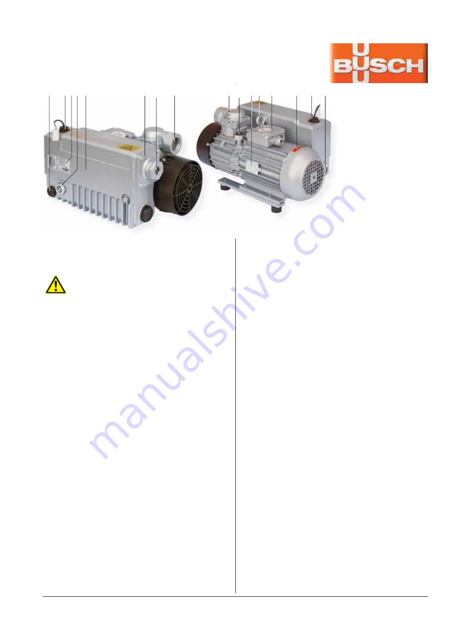
a b c d e f g h i j k l m n b d
a
Oil drain plug
b
Oil fill plug / Oil level switch
c
Nameplate, vacuum pump
d
Oil sight glasses
e
Oil separator
f
Exhaust cover plate
g
Gas discharge
h
Suction connection
i
Screen
j
Gas ballast
k
Nameplate, drive motor
l
Eye bolt
m Terminal box
n
Directional arrow
Summary of Contents for 160.0215
Page 8: ......
Page 10: ...ROBOT HP7E HP10E HP12E HP15E HP20E 0 Foreword 0 2 VEMAG 2010...
Page 22: ...ROBOT HP7E HP10E HP12E HP15E HP20E 2 Description 2 8 VEMAG 2010...
Page 32: ...ROBOT HP7E HP10E HP12E HP15E HP20E 3 Installation and commissioning 3 10 VEMAG 2010...
Page 58: ...ROBOT HP7E HP10E HP12E HP15E HP20E 6 Graphical control 6 12 VEMAG 2010 USB stick plugged in...
Page 60: ...ROBOT HP7E HP10E HP12E HP15E HP20E 6 Graphical control 6 14 VEMAG 2010 Mode group Mode View...
Page 64: ...ROBOT HP7E HP10E HP12E HP15E HP20E 6 Graphical control 6 18 VEMAG 2010...
Page 66: ...ROBOT HP7E HP10E HP12E HP15E HP20E 6 Graphical control 6 20 VEMAG 2010...
Page 68: ...ROBOT HP7E HP10E HP12E HP15E HP20E 6 Graphical control 6 22 VEMAG 2010...
Page 100: ...ROBOT HP7E HP10E HP12E HP15E HP20E 6 Graphical control 6 54 VEMAG 2010...
Page 102: ...ROBOT HP7E HP10E HP12E HP15E HP20E 6 Graphical control 6 56 VEMAG 2010...
Page 112: ...ROBOT HP7E HP10E HP12E HP15E HP20E 6 Graphical control 6 66 VEMAG 2010...
Page 128: ...ROBOT HP7E HP10E HP12E HP15E HP20E 7 Cleaning 7 16 VEMAG 2010...
Page 164: ...ROBOT HP7E HP10E HP12E HP15E HP20E 10 Appendix 10 12 VEMAG 2010 10 8 Hydraulic plan...
Page 168: ...ROBOT HP7E HP10E HP12E HP15E HP20E 10 Appendix 10 16 VEMAG 2010...