Valor 530 Direct Vent Installation Manual Download Page 8

Manufactured by Miles Industries Ltd., British Columbia, Canada 

4.2.3.


Rear vent connection, vertical vent rise with 
horizontal termination (Fig. 7) 

Can be used with either #551DVK standard vent kit or #984 
Dura-vent terminal cap and accessories. 
Adapter #817VAK, two 90° vent elbows #990B and Dura-vent 
pipe lengths will be required. 
(See venting options section of this manual). 

No more than two 90°elbows must be used. 

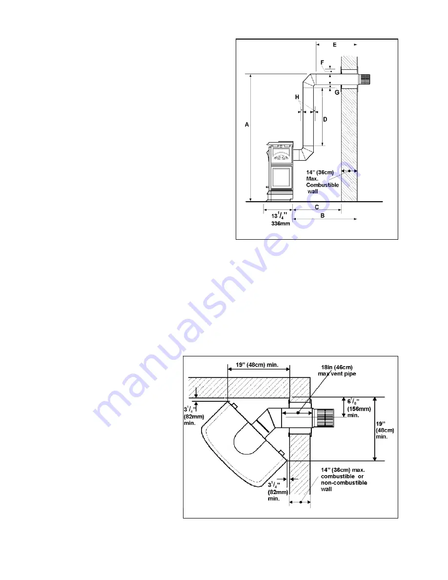
The location requirements are (See figure 7):- 


Minimum Maximum 

A

: From floor to top of 

vent duct 

3ft 7in 

(109cm) 

10ft 7in 

(323cm) 

B

: Back of appliance 

to outside wall 

- 5ft 

5in 

(165cm) 

C

: Back of appliance 

to inside wall 

14

1

/

8

in 

(36cm) 

D

: Vertical pipe run 

12in (30cm) 

8ft (244cm) 

E

: Horizontal pipe run 

(Total before and after 
elbows) 


- 4ft 

6in 

(137cm) 

F

: Clearance to 

combustible materials 
above horizontal pipe 
run 

2

5

/

8

in 

(6.7cm) 

G

: Clearance to 

combustible materials 
below horizontal pipe 
run 

1

5

/

16

in 

(3.3cm) 

H

: Clearance to 

combustible materials 
all round vertical pipe 
run and at sides of 
horizontal pipe run 

1

5

/

16

in 

(3.3cm) 


 Figure 7  


4.2.4.


Rear vent connection, vertical vent rise with horizontal snorkel termination 

For “semi-basement” situations where vertical vent rise does not raise horizontal termination sufficiently above ground level. 
The dimensional requirements in section 4.2.3 and figure 7 apply. 
Adapter #817VAK, two 90° vent elbows #990B, Dura-vent pipe lengths and a Dura-vent snorkel termination will be 
required. 
#942 Dura-vent wall thimble kit may also be 
necessary. 
(See venting options section of this manual). 

No more than two 90°elbows must be used. 


4.2.5.


Corner location, horizontal vent 
run only (Fig. 8) 

Can be used with either #551DVK standard 
vent kit or #984 Dura-vent terminal cap and 
accessories. 
Adapter #817VAK and 45° Dura-vent elbow 
will be required. 
(See venting options section of this manual). 

Be aware of the limited maximum vent pipe 
length and wall depth for this type of 
installation – See figure 8. 


 Figure 8 

Summary of Contents for 530 Direct Vent

Page 1: ...try to light any appliance Do not touch any electrical switch do not use any phone in your building Immediately call your gas supplier from a neighbor s phone Follow the gas supplier s instructions I...

Page 2: ...Models Only 27 8 11 Attaching Top Insulation Layers ZC Models only 28 8 12 Appliance Wall or Floor Fixing President FS only 28 9 INSTALLATIONS WITH HORIZONTAL TERMINATION INSTALLING TO WALL 29 9 1 Ins...

Page 3: ...e area well clear and free from combustible materials gasoline and other flammable vapors and liquids Never attempt to burn paper or any other material in the appliance The venting terminal must not b...

Page 4: ...l kit for non combustible wall thickness up to 26 66cm Combustible maximum 14 36cm 558FLK Through the wall Dura vent pipe insulation kit 817VAK Adapter for Dura vent pipes 984 Dura vent DV GS horizont...

Page 5: ...6 Mantle depth A Min Clearance B Up to 7 4 Above 7 up to 8 5 Above 8 up to 9 7 Above 9 up to10 8 Above 10 up to 12 9 More than 12 9 extra 1 for every 1 depth above 12 Mantle depth A Min Clearance B Up...

Page 6: ...d personnel should install the appliance The appliance when installed must be electrically grounded in accordance with local codes or in the absence of local codes with the National Electrical Code AN...

Page 7: ...xtending the full width and depth of the appliance 4 2 Venting configurations 4 2 1 Flat on wall Requires Valor vent kit 551DVK or Dura vent pipe length with adapter 817VAK and Dura vent terminal cap...

Page 8: ...ow horizontal pipe run 15 16in 3 3cm H Clearance to combustible materials all round vertical pipe run and at sides of horizontal pipe run 15 16in 3 3cm Figure 7 4 2 4 Rear vent connection vertical ven...

Page 9: ...tion Fig 10 Adapter 817VAK one 90 vent elbow 990B Dura vent pipe lengths a vertical vent terminal and roof flashing will be required Various other ceiling or roof items may be necessary depending on t...

Page 10: ...t not be connected to a chimney flue serving a separate solid fuel burning appliance Requires adapter 817VAK Co axial to co linear connector 923GCL two lengths of Chimney liner flex 2280 co linear ter...

Page 11: ...un 15 16in 3 3cm G Clearance to combustible materials all round vertical pipe run and at sides of horizontal pipe run 15 16in 3 3cm Figure 13 4 2 11 Top vent connection vertical vent rise with horizon...

Page 12: ...tion Figs 13 16 Figure 16 Can be used with either 551DVK standard vent kit or 984 Dura vent terminal cap and accessories Adapter 817VAK one 90 elbow 990B and Dura vent pipe lengths will be required Se...

Page 13: ...ons or allow useful space Adapter 817VAK two 45 vent elbows 984 wall straps a vertical vent terminal roof flashing and Dura vent pipe lengths will be required Various other ceiling or roof items may b...

Page 14: ...ioned 1 2 or 1 in front of the framing studding see figure 21 This enables a variety of wall finish thicknesses to blend with the appliance surround A non combustible hearth is not necessary in front...

Page 15: ...pipes 5 2 2 Flat on wall with snorkel termination Fig 23 For use on horizontal vent installations where the outside ground level is too close to the standard terminal Adapter 817VAK a Dura vent pipe...

Page 16: ...5 8 6 7cm G Clearance to combustible materials below horizontal pipe run 15 16 3 3cm H Clearance to combustible materials all round vertical pipe run and at sides of horizontal pipe run 15 16 3 3cm Fi...

Page 17: ...nation Fig 27 Figure 26 Adapter 817VAK one 90 vent elbow 990B Dura vent pipe lengths a vertical vent terminal and roof flashing will be required Various other ceiling or roof items may be necessary de...

Page 18: ...earance to combustible materials all round vertical pipe run and at sides of horizontal pipe run 15 16 3 3cm Figure 30 5 2 10 Top vent connection vertical vent rise with horizontal side termination Fi...

Page 19: ...pipe lengths will be required See venting section of this manual All vertical dimensions and clearance limits are as section 5 2 9 The minimum corner location is shown in fig 31 5 2 13 Top vent connec...

Page 20: ...or allow useful space Adapter 817VAK four 45 vent elbows 984 wall straps a vertical vent terminal roof flashing and Dura vent pipe lengths will be required Various other ceiling or roof items may be...

Page 21: ...clearance to ventilated soffit located above the terminal within a horizontal distance of 2 feet 60 cm from the center line of the terminal 18 46 E Clearance to unventilated soffit 12 30 F Clearance t...

Page 22: ...1 Top casting 1 Top infill plate Sides pack 1 Front casting unit 2 Side casting units 1 Top air deflector 1 Switch mounting bracket 2 Wall spacer brackets 2 Self cutting screws 4 Machine screws 4 Wash...

Page 23: ...spark The pilot burner and electrode unit is at the left end of the burner Push in the lighting knob and turn counter clockwise through the IGN position to PILOT A spark should flash across from the...

Page 24: ...er vent collar and seal by unscrewing 8 screws See figure 38 4 To make sure that the collars are axially aligned fit the Dura vent adapter 817VAK over the outer vent collar See figure 39 5 Position th...

Page 25: ...trate the inner tubes 3 Secure the adapter to the outer collar with two 6 thread cutting screws supplied Fig 40 8 5 2 For Installations With Dura Vent DV GS Co Linear Liners 1 Fit the Dura vent adapte...

Page 26: ...the Zero Clearance case These spacers are left and right handed Warning Failure to install the stand off spacers may result in a fire hazard 1 Remove the two screws near each of the rear top corners...

Page 27: ...oal appliances The correct restrictors to be fitted for each type of installation are shown in the table below To fit the restrictors remove the center screws from the rear ports and fit the restricto...

Page 28: ...f the appliance case with four thread cutting screws supplied Screw from outside through the access holes in the surround See figure 50 3 The outer surround has alternative locating tabs allowing its...

Page 29: ...n layers may cause a fire hazard and voids warranty 8 12 Appliance Wall or Floor Fixing President FS only The President FS can be secured to the wall and or floor if required The fixing positions are...

Page 30: ...izontal vent 9 3 Flat On Wall Installations With Valor 551DVK Terminal 1 Cut the vent terminal pipe unit to size Fig 52 Manufactured by Miles Industries Ltd British Columbia Canada 29 Important The dr...

Page 31: ...e wall 4 Screw the plate to the wall with 4 screws provided 9 4 1 Installing Appliance to Wall 1 Slide the appliance fully up to the wall 2 Bend the outer wall plate tab as shown in figure 54 Place th...

Page 32: ...d position 8 A ceiling firestop must be installed at the second floor and higher floors A ceiling support should be used below the flat ceiling To install the firestop support cut and frame a 10 254mm...

Page 33: ...haped terminals on the 20ft wall switch wires connect with the burner control unit Route the wires round the back of the valve to the wall switch location The connections to the wall switch are shown...

Page 34: ...to the terminal block Connect the black wire to the terminal opposite the brown wire Connect the wire with the white stripe to the terminal opposite the yellow wire See figure 60b Route the wires rou...

Page 35: ...ct the batteries in the remote control receiver until the wires are connected to the burner control unit A short circuit could result in destruction of the electrical components Figure 65 A set of fou...

Page 36: ...NPT tapping must be installed in the line The tapping must be accessible for test gauge connection and be immediately upstream of the gas supply connection to the appliance 7 Pressure test the supply...

Page 37: ...ons In a few unusual installations performance may be improved by adjusting the aeration The need for adjustment should be determined by operating the appliance with the ceramic fuel effects and windo...

Page 38: ...re 72 1 Locate the ceramic rear wall in the channel at back of the firebox and flat against the back of the firebox See figure 69 2 Locate the side walls in the channels at the sides of the firebox Se...

Page 39: ...re 74 4 Place the right side log in the hollow at right of the base log Rest the narrow nose of this log on the projection at front center of the base log It is important that the narrow nose does not...

Page 40: ...t of the firebox See figure 78 3 Place the right front coal behind the metal lip at the front of the firebox Its left side should rest over the projection on the left front coal See figure 79 4 The ce...

Page 41: ...indow and tighten to secure the bottom of the window See figure 82 4 Pull the top of the window forward and release to check that the window opens slightly and returns in the event of a delayed igniti...

Page 42: ...cessary However in a very few instances performance may be improved by adjusting the aeration by sliding the shutter See figure 68 Evaluate the aeration only after the unit has warmed up approximately...

Page 43: ...g making sure that the corners locate as shown in figure 86 Figure 85 3 If rear vent connection Fit the top infill casting See figure 87 4 If necessary the appliance can be leveled by the adjustment b...

Page 44: ...ides of the front unit the top of the front can be moved forward to allow the tiling to go behind the top To move the top slacken the clamping bolts slide the top forward retighten the bolts See figur...

Reviews: