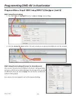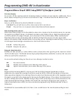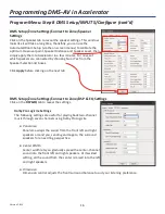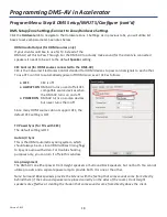
5
Version 1.612
Start with all AC power cords unplugged from their designated AC outlets.
1.
Place the DMS-AV with a
minimum of 3” of unobstructed air space above
it. Ensure that the client
cannot obstruct or spill liquid into the chassis.
2.
From each source device,
connect the A/V cables
, which may include: Composite, Component, HDMI,
Digital Coax, Toslink Optical and or Analog Audio RCA. Ensure that the correct IR, RS232, Network,
Relay or Sensor connection is made to the MRX-10. The DMS-AV cannot control anything, only the unit
provides control.
SNP-1: If the client would like to listen to music and view the SNP-1’s TV GUI, you must connect the
component cables from the SNP-1 to the DMS-AV. If the client does not care to use the TV GUI, do
NOT connect the SNP-1 to the DMS-AV. For more information, refer to pages 19 and 20.
3. Connect speaker cables
from the DMS-AV’s speaker outputs to the appropriate speakers.
Remember,
the system can include Front Height or Surround Back but not both (even the addition of another
power amp cannot provide both; the processor can only be configured for one or the other).
4.
Connect the appropriate video cables from the DMS-AV’s Video Output(s) to the TV/Video monitor’s
Input(s).
Remember, the DMS-AV will scale all composite or component sources to HDMI so feel free
to connect legacy video sources.
5.
The DMS-AV must be connected to the MFS (MAC Filtering Switch) of your Total Control system, when
it is configured to receive and send DMS Streams (even in a one room system with an SNP-1,
streaming will occur)
. Connect an Ethernet cable from the DMS-AV to the MFS-8 or MFSPOE-8
.
The
MFS-8 must be connected to the (LAN) local area network. If you need more than eight network
connections, connect any type of simple network switch to any of the MFS-8’s eight LAN ports. If you
are using multiple MFS-8’s (unnecessary, but perfectly workable) connect only ONE MFS-8 to the home
network via the LAN port, all other MFS units can be linked to the first using ONLY the expansion ports
(only one MFS unit will use the LAN port). All other MFS-8’s or MFSPOE-8’s are connected using only
the 8 expansion ports.
6.
Plug the AC power cords
for the DMS-AV and all other devices into their designated AC outlets.
7.
Power
ON
the DMS-AV using the back panel
Main Power
switch.
8.
Bring the DMS-AV out of Standby mode, via the front panel
Standby
button.
9.
Power
ON
the TV and any source components.
Note:
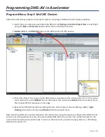
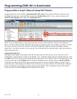
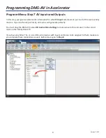
Before you can begin to test, you must first program Accelerator.
The manual included in the
box refers to DMS System ToolBox as a separate app. However, it is actually incorporated into
Accelerator.
Overview
Pre-programming Checklist
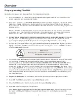
Must Know!
The Composite and HDMI sources are not converted
to Component Video Output.

