GRAPHICS SOFTWARE SETUP
Section 3-2
Power Control through Color Selection
The laser system allows the use of 8 different colors to access 8 different power settings when cutting
and engraving. The printer driver controls this feature. When using this power change feature with
driver, the colors that are used MUST exactly match the colors listed in the driver. The colors are black,
red, green, yellow, blue, magenta, cyan, and orange. Some programs will provide these basic colors pre-
defined and other programs may require the creation of each of the colors by defining them in RGB. If
you are using CorelDRAW we have made our own custom palette and placed the file on the Software
Installation CD-ROM. Please refer to the software setup instructions for your specific version of
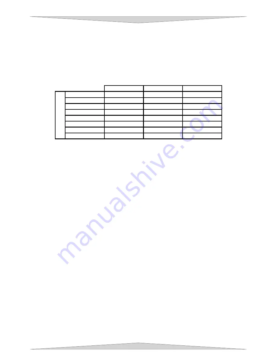
CorelDRAW. If you are using other graphics software and need to mix your own colors, use the chart
below to create them.
RED (R)
GREEN (G)
BLUE (B)
BLACK
0 0 0
RED 255 0
0
GREEN
0 255 0
YELLOW 255
255
0
BLUE 0 0 255
MAGENTA
255 0 255
CYAN 0 255 255
COL
ORS
ORANGE 255
102
0
If using a color other than the exact colors listed above, the driver will attempt to match it to a color in the
driver that it most closely resembles. The driver will then use that color’s power setting and apply a
halftone pattern to represent the original color’s shade. For example, if using a color like pink to fill a
rectangle, the driver takes a reading of the percentage of different colors used to create that color and will
use the power setting assigned to one of the eight colors of the driver that it most closely resembles. It
might be expected that the driver will use the power setting assigned to the color red but instead the
driver may choose the magenta setting and halftone the rectangle as a representation of the pink color’s
lighter shade. To prevent the incorrect assignment of laser power, be sure to use the correct colors. If
using graphics with colors other than the eight listed above or to simplify the assignment of power
settings, try using the Clipart Mode feature in the driver. This feature will cause the system to only use
the power setting assigned to the color black and halftone all of the other colors.
Outlines and Fills
The driver distinguishes between raster mode (engraving) and vector mode (cutting) by the type of
graphic artwork being used. Basically, all graphics other than outlines of very thin line widths will be
interpreted as engraved images and the raster mode will be used for output. If laser cutting is desired,
set the line thickness of the lines that are drawn in the graphics software to .001 inches (.025 mm) or the
smallest possible line thickness that is available. The printer driver will interpret these objects as vectors
and will cut them out providing that your software has the capability of vector output. Basically, all
software programs have the ability to provide raster output. However, not all programs have the ability to
provide vector output even if you set the line width to the smallest thickness possible. Check with Section
2-9 of this manual for software that can vector output. The use of color fills or bitmaps will cause the laser
system to engrave. The combination of engraving and cutting is available in most graphics software. We
suggest that when combining engraving and cutting objects, use different colors for the fills and outlines
since engraving requires different power settings than cutting objects. One thing to keep in mind when
creating cutting objects is that if the outline thickness is set too thick, the driver might interpret the outline
as a filled object and will engrave the outline instead of cutting. This might be desirable if engraving thick
outlines is necessary. The outline thickness at which the driver will interpret cut lines as filled objects is
dependent on the software used. Usually, any line thickness .008 inches (.2 mm) or greater will engrave.
The only way to determine the cross over point for line thickness is to experiment with different line
widths. Software programs that do not have outline capabilities definitely will not have the ability to cut.
Image Processing Order
When cutting or engraving a graphic image, the laser system will perform all engraving first, and then
proceed to vector cutting. Raster engraving will proceed in the exact order of the colors listed in the
driver. For example, all black filled objects will engrave first, then all red filled objects, then all green filled
objects and so on. When all engraved objects have been completed, the laser system will proceed to
Summary of Contents for PLS3.60
Page 8: ......
Page 20: ...SAFETY Section 1 12 ...
Page 21: ...Part 1 Initial Setup ...
Page 22: ......
Page 30: ...INSTALLATION Section 2 10 ...
Page 44: ...GRAPHICS SOFTWARE SETUP Section 3 14 ...
Page 58: ...MAKING A SAMPLE Section 5 4 ...
Page 59: ...Part 2 Laser System Essentials ...
Page 60: ......
Page 70: ...BASIC SYSTEM FEATURES Section 6 12 ...
Page 76: ...BASIC MAINTENANCE Section 7 6 ...
Page 77: ...Part 3 Accessories ...
Page 78: ......
Page 95: ...Part 4 Advanced User ...
Page 96: ......


