background image

ASSEMBLING THE PLS 

Section 4-5 


Detaching laser system from cart 


1. 

Make sure unit is unplugged from an 
electrical outlet. 

2. 

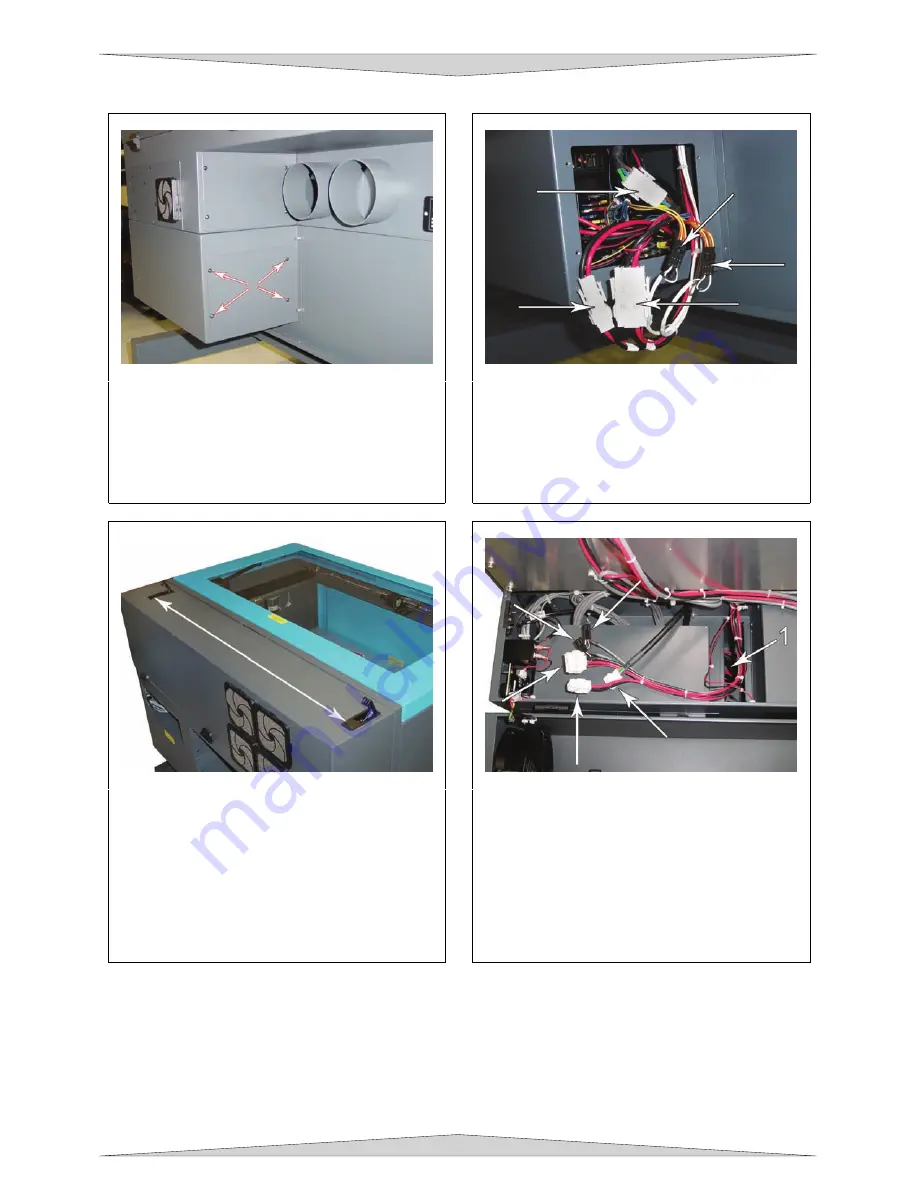
At the back of the system, locate the four 
screws; remove them and the cover plate. 


3. 

Locate the three white connectors and the 
two black connectors.  Unplug all five 
connectors.  They are held in place by 
latches so you will squeeze on the sides in 
order to release the latches to pull the 
connectors off. 


4. 

Open the rear cover by pressing down on 
the button part of the latches until the 
latches pop up. 

5. 

Fold the rear cover down to a resting 
position. 


6. 

Locate the cavity (1) where the cables 
reside.  Gently pull the cables upwards and 
rest them on top as the diagram indicates. 

7. 

Close and re-latch the rear cover. 

8. 

Remove any packing materials or 
accessories from inside the laser system. 

9. 

Using strong shipping tape or rope, tape the 
front door closed so that it does not open up 
when you tilt it. 


Summary of Contents for PLS3.60

Page 1: ...ce Manual System Serial Number _____________ Located on the back of the machine and inside the front door Laser Tube Serial Number s ______________ ______________ Universal Laser Systems Inc 16008 North 81st Street Scottsdale AZ 85260 USA Technical Support Department Phone 480 609 0297 Fax 480 609 1203 Web Based Email Support www ulsinc com March 2008 ...

Page 2: ...he possibility of such damages or claims WARNING UNIVERSAL LASER SYSTEMS PRODUCTS ARE NOT DESIGNED TESTED INTENDED OR AUTHORIZED FOR USE IN ANY MEDICAL APPLICATIONS SURGICAL APPLICATIONS MEDICAL DEVICE MANUFACTURING OR ANY SIMILAR PROCEDURE OR PROCESS REQUIRING APPROVAL TESTING OR CERTIFICATION BY THE UNITED STATES FOOD AND DRUG ADMINISTRATION OR OTHER SIMILAR GOVERNMENTAL ENTITIES SHOULD THE BUYE...

Page 3: ...e problem began all of a sudden worsened over time or began after you performed any recent maintenance Also be prepared to describe all pertinent information about the computer being used such as software ULS printer driver version computer operating system and computer type Step 2 Make sure that you have the serial number of the laser system available The serial number tags are located on the bac...

Page 4: ...5ºF 35º C Operating Humidity Non condensing Electrical Power Single Phase 110 230V AC 10 5 Amp 50 60 Hz Grounded earthed and stable surge and spike protected High pressure vacuum blower capable of Particulate Odor Outside Ventilated Exhaust System 250 CFM cubic feet per minute 6 inches static pressure 425m3 hr at 1 5kPa 500 CFM cubic feet per minute 6 inches static pressure 850m3 hr at 1 5kPa Comp...

Page 5: ...ows XP or Windows Vista 32 bit version only Interconnection USB 2 0 High Speed port Cabinet Style Floor Standing Laser Options 10 25 30 35 40 45 50 55 and 60 watts 10 25 30 35 40 45 50 55 and 60 watts equipped for two lasers Power Requirements 110V 10A 230V 5A 230V 15A Size inch 36W x 38T x 30D 91 4cm W x 96 5cm T x 76 2cm D 36W x 39T x 36 5D 91 4cm W x 99 1cm T x 92 7cm D 44W x 39T x 37 5D 111 8c...

Page 6: ...8 CorelDRAW X3 3 10 AutoCAD 2000i 2002 2004 3 12 Adobe Illustrator CS 3 13 Section 4 Assembling the PLS System Assembly PLS3 60 and PLS4 60 4 1 System Assembly PLS6 60 and PLS6 120D 4 4 Finalizing the Connections 4 8 Checking Beam Alignment All PLS laser systems 4 10 Section 5 Making a Sample Step 1 Loading and Positioning the Material 5 1 Step 2 Creating the Graphic 5 1 Step 3 Printing to the Las...

Page 7: ...Compressor 8 8 Dual Head 8 9 Honeycomb Cutting Table 8 12 Focus Lens Kits 8 14 Rotary Fixture 8 15 Part 4 Advanced User Section 9 Advanced System Operation Printer Driver Controls 9 3 Manual Control Tab 9 4 Focusing Methods 9 17 Making a Sample Manual Control Tab 9 19 ...

Page 8: ......

Page 9: ...rational requirements and safety guidelines listed in this manual may increase this risk EXPOSURE TO THE LASER BEAM MAY CAUSE PHYSICAL BURNS AND CAN CAUSE SEVERE EYE DAMAGE Proper use and care of this system are essential to safe operation NEVER OPERATE THE LASER SYSTEM WITHOUT CONSTANT SUPERVISION OF THE CUTTING AND ETCHING PROCESS Exposure to the laser beam may cause ignition of combustible mate...

Page 10: ... EASILY ACCESSIBLE WALL SOCKET OUTLET To disconnect the equipment from the supply mains the power cord shall be unplugged from the wall outlet or main power inlet appliance coupler of the unit THIS DEVICE IS SPECIFICALLY DESIGNED TO COMPLY WITH CDRH PERFORMANCE REQUIREMENTS UNDER 21 CFR 1040 10 AND 1040 11 CDRH is the Center for the Devices of Radiological Health division of the Food and Drug Admi...

Page 11: ... damaged or have been removed for any reason DO NOT OPERATE the laser system and immediately contact Universal Laser Systems Inc for a free replacement Labels are NOT to scale Model No Serial No Made in USA Manufactured Laser Processing System Manufactured By Scottsdale Arizona LASER SYSTEMS INC XXX XXXX XXXXX XXX XXXX SERIAL XXXXX DATE XXXXX 221 0002 0 221 0007 0 WARNING NEVER OPERATE THE LASER S...

Page 12: ...221 0019 0 221 0020 0 INPUT POWER 110 VAC 50 60 Hz 10 A 221 0021 0 221 0022 0 INPUT POWER 230 VAC 50 60 Hz 15 A THIS LASER MANUFACTURED BY UNIVERSAL LASER SYSTEMS 16008 N 81ST ST SCOTTSDALE AZ 85260 USA IS A CLASS 4 DEVICE AND DOES NOT COMPLY WITH U S CODE 21 CFR SUBCHAPTER J OR EUROPEAN STANDARD EN 60825 1 1994 IS DESIGNED FOR USE ONLYAS A COMPONENT IN A ULS LASER SYSTEM THIS LASER THIS LASER PRO...

Page 13: ...HIS SYSTEM CREATES A SERIOUS SAFETY AND OR FIRE HAZARD DO NOT CONNECT ANY GAS SOURCES EXCEEDING 75 PSI 5 ATM PRESSURE UNIVERSAL LASER SYSTEMS ASSUMES NO RESPONSIBILITY ARISING FROM THE IMPROPER USE OF THIS SYSTEM 221 0036 0 221 0037 0 THIS PRODUCT IS MANUFACTURED UNDER ONE OR MORE OF U S PATENTS 5 051 558 5 661 746 5 754 575 5 867 517 5 881 087 5 894 493 5 901 167 5 982 803 6 181 719 6 313 433 6 3...

Page 14: ...3 60 PLS4 60 PLS6 60 Label Placement 221 0018 0 221 0007 0 221 0031 0 221 0017 0 221 0086 0 221 0087 0 221 0088 0 221 0089 0 Laser Tube 221 0016 0 221 0012 0 221 0013 0 221 0033 0 221 0034 0 221 0022 0 221 0036 0 221 0018 0 ...

Page 15: ...SAFETY Section 1 7 221 0020 0 221 0021 0 221 0016 0 221 0037 0 221 0016 0 221 0020 0 221 0002 0 221 0015 0 221 0065 0 221 0081 0 Back View of laser system ...

Page 16: ...ction 1 8 PLS6 120D Label Placement 221 0018 0 221 0007 0 221 0031 0 221 0017 0 221 0086 0 221 0087 0 221 0088 0 221 0089 0 Laser Tube 221 0016 0 221 0012 0 221 0013 0 221 0033 0 221 0034 0 221 0018 0 221 0007 0 ...

Page 17: ... Section 1 9 221 0016 0 221 0021 0 Back View of laser system Rear cover open 221 0016 0 221 0020 0 221 0024 0 221 0037 0 221 0002 0 221 0015 0 221 0065 0 221 0081 0 Back View of laser system Rear cover closed ...

Page 18: ...ry Directive 2002 95 EEC ROHS Directive 2002 96 ECC WEEE Directive based on the standards listed Standards Used Safety EN 60950 2002 EN 60825 1 2002 Class 3R EMC EN 55024 1998 Class A EN 55022 2003 Class A EN 61000 3 2 2001 class A EN 61000 3 3 2002 EN 61000 4 2 2001 4kV CD 8kV AD EN 61000 4 3 2003 3 or 10 V m EN 61000 4 4 2002 1 or 2 kV power line EN 61000 4 5 2001 class 3 EN 61000 4 6 3 or 10Vrm...

Page 19: ...instructions may cause harmful interference to radio communications Operation of this equipment in a residential area is likely to cause harmful interference in which case the user will be required to correct the interference at his or her own expense Users should be aware that changes or modifications to this equipment not expressly approved by the manufacturer could void the user s authority to ...

Page 20: ...SAFETY Section 1 12 ...

Page 21: ...Part 1 Initial Setup ...

Page 22: ......

Page 23: ...from any type of sandblasting sanding oily or any other machinery that produces airborne particles Avoid small enclosed non ventilated areas Some materials after laser engraving or cutting continue emitting fumes for several minutes after processing Having these materials present in a confined unventilated room can contaminate the room For best results since the lasers are air cooled we recommend ...

Page 24: ...tance traveled between the blower and the laser system The tubing should be smooth walled and have as few 90 degree bends as possible Install a gate to control airflow and to close off the exhaust from the outside environment when the laser is not in use Place this gate within 5 10 feet from the laser system Use a short piece of industrial grade wire reinforced rubber tubing to connect the end of ...

Page 25: ...wire reinforced industrial grade rubber hose 7 On Off switch 8 Computer user supplied PLS6 60 and PLS6 120D 1 2 3 4 5 6 9 8 3 4 5 6 7 6 8 7 10 1 Exhaust blower mounted outside 2 Weatherproof shield 3 Rigid ducting matching the diameter of the blower inlet 4 Reducer to 4 inches 5 Y pipe 6 Shut off or air flow gate s 7 Flexible wire reinforced industrial grade rubber hose 8 Connection to laser 9 On ...

Page 26: ...un Windows Vista NOTE Some computer motherboard manufacturers USB ports DO NOT comply with USB 2 0 High Speed standards This may cause erratic behavior from the PLS such as freezing and lock ups Other USB peripheral devices that demand a large amount of computer processing power may slow down the operation and productivity of the PLS We recommended not using these devices while operating the PLS N...

Page 27: ... in the box Monitor power Click the button Power 5 Select the tab Power Schemes 6 For the Power Scheme in use select Never for all the setting options Turn off monitor Turn off hard disks System standby and System hibernates 7 Click Apply then OK on both open windows If you have further questions on how to configure or upgrade Windows XP please contact Microsoft Corporation NOTE Your chosen graphi...

Page 28: ...tion process will begin indicated by a progress bar Be patient Loading the files can take a few minutes depending on your processor speed 3 You will be prompted to select your model Select the laser engraver you are installing on the computer then click on Ok The software will continue loading as indicated by a progress bar a If the incorrect model is selected you will receive an error message lat...

Page 29: ...e package which contains all the software necessary to operate the PLS to its fullest capability Earlier versions of CorelDRAW have experienced problems with the XP operating system which in turn causes problems with the operation of the PLS As a result ULS recommends CorelDRAW 12 over earlier versions Whether you decide to use CorelDRAW12 or a different graphics software package it is critical th...

Page 30: ...INSTALLATION Section 2 10 ...

Page 31: ... specifications EXACTLY otherwise the artwork may not print correctly When setting page orientation and driver orientation to Landscape mode the laser system will operate in the horizontal direction left to right If page orientation and driver orientation is set to Portrait mode the laser system will operate in the vertical direction front to back The laser system is designed to operate best in th...

Page 32: ...other colors Outlines and Fills The driver distinguishes between raster mode engraving and vector mode cutting by the type of graphic artwork being used Basically all graphics other than outlines of very thin line widths will be interpreted as engraved images and the raster mode will be used for output If laser cutting is desired set the line thickness of the lines that are drawn in the graphics s...

Page 33: ...s and starts If the engraving object is longer than it is tall rotating the graphic 90 degrees and placing the material in the laser system sideways can achieve a greater engraving speed Be aware that some graphics programs do not allow the rotation of bitmaps In this case it may be necessary to use a bitmap image processing software to first rotate the bitmap before importing the bitmap into the ...

Page 34: ...others Once the image is converted by your program save and print it directly from that program or import it into your graphics program and print it from there Essentially a Halftone image and an Error Diffusion image are actually both monochrome images and can be treated as such If you decide not convert the grayscale image to a monochrome image in your bitmap image editing program then the drive...

Page 35: ...fer to your graphics software on how to convert fonts However postscript textures and postscript fills cannot be converted and will not print to the laser system Specific Software Setup Some graphics software programs require a special setup procedure in order for the software to function correctly with the ULS printer driver In the following pages you will find setup instructions for the most pop...

Page 36: ... Open CorelDraw and start a new graphic 8 In the main menu at the top of the screen click on Window then Color Palettes and then click on None Once again click on Window then Color Palettes and then click on Open Palette After the palette pop up box appears from the Files of type dropdown list choose either Custom Palette cpl or Process Palette pal then double click on the ULS palette The color pa...

Page 37: ...ave Options as Defaults for New Documents Make sure ALL the options listed are CHECKED then click OK 15 The setup defaults for CorelDRAW 11 are now complete Whenever you start a new document all of the default settings that we had setup will automatically apply to the new document Next proceed to section 4 for laser system assembly ...

Page 38: ...Printer Driver must be loaded before continuing Please refer to Section 2 8 on the manual on how to install the driver If you have already installed the printer driver you will need to re insert the Software Installation CD ROM back into your CD drive at this time 5 Using Windows Explorer locate the file named ULS CPL and ULS PAL on the Software Installation CD ROM and copy this file over to the C...

Page 39: ...h dropdown box and click Hairline The units can be inches millimeters or anything else you prefer Click OK to close the Outline Pen dialog box 12 In the top menu click Tools and then click Color Management Click on the down arrow to expand the Style dropdown list Click Color Management Off and then click OK 13 Finally at the top of the screen click on Tools then Options then Document and then sele...

Page 40: ...driver If you have already installed the printer driver you will need to re insert the Software Installation CD ROM back into your CD drive at this time 5 Using Windows Explorer locate the file named ULS CPL and ULS PAL on the Software Installation CD ROM and copy these files over to the C Program Files Corel Corel Graphics SUITE X3 13 Languages EN Custom Data Palettes folder Note ULS CPL may not ...

Page 41: ...olor dropdown box to expand the list and click on the color red Click the down arrow in the Width dropdown box to expand the list and click Hairline The units can be Inches millimeters or anything else you prefer Click OK to close the Outline Pen dialog box 12 In the top menu click Tools and then click Color Management Click on the down arrow to expand the Settings dropdown list Click Color Manage...

Page 42: ...0 Edit the PMP file name if you desire then click Next DO NOT click the Print a Test Page button click Finish Click OK to exit the Plotter Configuration Editor window and then click Finish 11 Click File Page Setup and then select the Plotter Configuration name pc3 name not the driver from the dropdown list 12 If you would like to change the drivers settings click the Properties button then click t...

Page 43: ...are page that is equal to the width of your laser systems field For example if your laser system has a 24 x 12 inch field then set the page setup in Adobe to 24 x 24 inch Portrait mode not Landscape If you laser system has a 32 x 18 inch field set the page setup in Adobe to 32 x 32 Portrait 7 Now place your graphics ONLY within the top portion of your page in Adobe Don t use the bottom portion tha...

Page 44: ...GRAPHICS SOFTWARE SETUP Section 3 14 ...

Page 45: ...IFTING THIS DEVICE Obtain assistance from 3 or 4 additional people when lifting or carrying secure motion system and doors Severe bodily injury may occur if improper lifting techniques are applied or the system is dropped System Assembly PLS3 60 and PLS4 60 1 2 2 3 3 4 9 5 5 6 6 5 5 10 10 10 10 10 10 7 8 7 8 Cart 1 Back panel 2 Legs both are identical 3 Side Panels 2 4 Shelf Panel 5 1 4 20 x socke...

Page 46: ...Securely tighten all the screws and re check 6 Attach your exhaust system s flexible rubber hose to the exhaust port at the rear of the laser system and secure with a hose clamp 7 Locate the laser system in its final resting location 8 Place a bubble level across the rear legs 1 Adjust the caster height using the adjustment screw 2 until both the rear part and the front part of the legs are level ...

Page 47: ...ent fork has two plates one small 4 and one large 5 Locate the gap between the two plates 6 3 Observe the V groove along the upper 3 and lower 2 part of the laser cartridge and the alignment plate 1 at the end 4 Pick up the laser cartridge by the sides and tilt it downward on a 30 degree angle Mount the cartridge onto the mounting blocks by placing the upper V groove on top of the mounting blocks ...

Page 48: ...d to Section 4 8 once the laser tube has been installed System Assembly PLS6 60 and PLS6 120D Unpack the laser system from its packaging If the doorway is not wide enough to allow to you roll the laser system through it the system MUST be detached from the cart stand rotated sideways passed through the doorway then re attached to the cart stand Section 4 5 If your doorway is wide enough you can sk...

Page 49: ...e sides in order to release the latches to pull the connectors off 4 Open the rear cover by pressing down on the button part of the latches until the latches pop up 5 Fold the rear cover down to a resting position 6 Locate the cavity 1 where the cables reside Gently pull the cables upwards and rest them on top as the diagram indicates 7 Close and re latch the rear cover 8 Remove any packing materi...

Page 50: ...the latches until they click Leveling the System Move the laser system to the desired operating location If the floor underneath the laser system at this location is uneven the casters must be adjusted Uneven flooring can cause mechanical problems with the operation of the motion system which can seriously affect engraving or cutting quality 1 Place a bubble level across the back 1 legs Adjust the...

Page 51: ...u have purchased two lasers mount the first cartridge onto the LOWER mounting blocks first Single laser users should mount the laser in the top position Tilt the laser cartridge downward on a 30 degree angle Place the upper V groove 4 of the cartridge on top of the mounting blocks 1 Slide the cartridge to the right until the alignment plate 5 of the laser cartridge makes contact with the inside of...

Page 52: ...t the laser systems power cord and your computers power cord to a grounded electrical source International users may need to connect an adapter to the power cord to be able to plug it into their power source MAKE SURE THAT YOU ATTACH THE ADAPTER CORRECTLY TO THE POWER CORD AND THAT YOUR POWER SOURCE IS PROPERLY GROUNDED EARTHED OTHERWISE SERIOUS DAMAGE CAN OCCUR TO THE LASER SYSTEM DO NOT POWER ON...

Page 53: ...the rear of the laser system DO NOT USE ANY ADAPTERS EXTENSION CABLES SWITCH BOXES ZIP DRIVE OR ANY DEVICE BETWEEN THE COMPUTERS USB PORT AND THE PORT ON THE LASER SYSTEM OTHERWISE DAMAGE TO THE COMP L a Connect the USB cable provided between the USB port of the computer and b After connecting the USB cord the Found New Hardware Wizard will open You will be asked if Windows should connect to the W...

Page 54: ...ss the 3 4 hole in the focus carriage 1 Gently rub the tape around the edge of the hole so that you can see the then close the top door 3 Power ON the laser system switch on the back right hand side r on your computer and verify that the blue shaped icon is present on the taskbar If not activate it by double r of the hole please contact our Laser beam alignment is now complete Power OFF the laser ...

Page 55: ...hat the page size in your graphic software matches the ULS printer driver s maximum page size We recommend that you always leave the page size set to the maximum for your system and position your graphic accordingly Create some text with a BLACK colored fill and NO outline For example type in the word KEYCHAIN Draw an outline box around the text color the outline RED give the outline a thickness o...

Page 56: ...you have made all the appropriate selections and entered the material thickness click OK The printer driver closes and reverts back to the Print Dialog box and now click on PRINT Figure 4 As the print job is being created a small printer icon will appear in your taskbar in the lower right corner of your computer screen Once the icon disappears the print job is completed and is now stored on your h...

Page 57: ...acuate through the exhaust system Open the top door and remove the material Some materials will continue to emit fumes from several minutes to sometimes hours after the engraving or cutting process is completed We recommend that you relocate these materials to a well ventilated and unoccupied area WARNING Some materials when engraved or cut with a laser can produce toxic and caustic fumes We sugge...

Page 58: ...MAKING A SAMPLE Section 5 4 ...

Page 59: ...Part 2 Laser System Essentials ...

Page 60: ......

Page 61: ...on your computers desktop screen You can access the UCP at anytime by left clicking once on the icon in the taskbar The following describes the features of each tab of the UCP Viewer Tab Selecting this tab will allow you to preview your file and control features of the laser system System Controls The upper right side contains the software version of the Keypad buttons found on the PLS laser syste...

Page 62: ...pe in the X and Y coordinates Once you have finished typing in the coordinate s press the GO button within the focus window Estimate View drop down list The estimate feature approximately calculates the amount of time it will take the PLS to finish the engraving or vector cutting job The more complex the ngraving job is the longer it will take to finish and visa versa e Relocate View drop down lis...

Page 63: ...S Focus Carriage If you change lenses available accessory other than the standard 2 0 then you MUST select the value that matches your installed lens and calibrate drive and save print jobs as efm files The PURGE button deletes ALL cached drive If the Permanent box is marked this indicates that the selected file will not System Tab Selecting this tab will allow the configuration of certain feature...

Page 64: ... Diagnostics Tab The Diagnostics Tab displays important inform about your laser system and personal computer ENGRAVER shows the current Firmware and FPGA version being used It also displays the Serial Number of your laser system The Serial Number is needed when c Support Department at ULS AIR ASSIST displays the current device being used shown by a green check mark to supply compressed air to the ...

Page 65: ...nning the PAUSE button halts the engraving or cutting process and the focus carriage will move to its home position in the upper right corner of the engraving area If the PAUSE button is pressed again after the initial pause it will resume cutting or engraving again at the location where the motion system was paused Please wait for the motion system to stop and m sition it stoppe SELECT ESCAPE Thi...

Page 66: ...croll through the File Name and timer A Color B Power C Speed D and PPI E The Power Speed and PPI of the file being engraved can be changed on the fly by pressing the LEFT and RIGHT buttons as the file is being processed The t th XY This menu displays the current position of the focus carriage according to the ru Z This menu displays the current position of the engraving tab Printer Driver Control...

Page 67: ...to the printer driver Th g NOTE This part of the Materials Database requires you to have knowledge of the fe Material Editing This feature gives you further control over the Materials Database and has similar features as the Manual Control Tab in the printer driver Section 9 Custom categories and materials can be added and deleted They can also be modified to your specific requirements Once you ha...

Page 68: ...s Database Tab active Select one of the existing Categories on the left and click on the NEW button The Material Editing window appears From the Category drop down menu list on the left select New Category The Material Category window appears allowing you to type a name of the new category in the blank space A Category ID 900 999 will automatically be assigned once a new category is made Click on ...

Page 69: ...sired Custom If you prop up the material you are going to engrave on a surface othe NOTE The Materials Database is meant for the novice and beginning user As a user operates the laser system and understands how it works he or she may edit the existing Materials Database for further control Editing the Materials Databa m If you would like to use the Manual Control Tab refer to Part 4 Advanced User ...

Page 70: ...BASIC SYSTEM FEATURES Section 6 12 ...

Page 71: ... procedures Motion System Components Diagram NOTE 2 Mirror Cover and X axis Motor Cover Plates have been removed for visibility 1 Focus carriage 3 10 7 8 9 1 2 4 5 6 11 12 13 14 15 16 17 18 19 20 21 18 22 23 14 16 2 X axis bearing 3 3 3 mirror inside cover plate 17 Y axis drive gear 2 one on right side one on left side 18 Y axis shaft 2 one on right side one on left side 19 Y axis shaft flex coupl...

Page 72: ...e bearing tracks will cause the bearings to wear and the engraving quality to become rough After the rails and tracks are cleaned use a clean swab or paper towel and soap solution to clean all of the bearings by holding the swab against each bearing and moving the motion system by hand to roll the bearings against the swab There are seven bearings in the system three 3 on the focus carriage two 2 ...

Page 73: ... To gain access to the 3 mirror 3 and the focus lens 4 hold the front cover 2 with one hand and remove the three thumbscrews with the other hand Pull the front cover straight out The 3 mirror and the focus lens are both mounted to the front cover Tilt the front cover enough to enable you to apply the lens cleaning solution directly to the 3 mirror and to the focus lens Flood the reflective surface...

Page 74: ...d PLS6 120D s exhaust plenums are removed in the same fashion but these two laser systems come with two exhaust plenums Cooling Fan Filters PLS3 60 and PLS 4 60 This air cooled laser system will require periodic cleaning of the cooling fan filters Since ambient air is used to cool the laser cartridge the air must be filtered before it enters the inside of the laser system Dirt or dust contaminatio...

Page 75: ...ependent on the type of material being run the quantity of material being removed the hours of operation and the quality of the exhaust blower it must be user defined As a starting point we recommend the following schedule As necessary Engraving table Main enclosure Top door window Every 8 hours of engraving Clean X axis and Y axis bearings Clean X axis and Y axis rails and bearing tracks Clean X ...

Page 76: ...BASIC MAINTENANCE Section 7 6 ...

Page 77: ...Part 3 Accessories ...

Page 78: ......

Page 79: ...system The use of this Air Assist has been known to increase the frequency of cleaning maintenance due to debris being blown around inside the engraving area during laser processing Standard and Computer Controlled styles There are two styles of Air Assist standard and computer controlled The computer controlled option uses three solenoids to control low pressure air high pressure air and an exter...

Page 80: ...5 to a particulate filter 6 desiccant dryer 7 and then to an oil free compressed air source 8 Computer Controlled Air Assist style In the left rear part of the system you will find the Air Assist control box Attached to the box not shown in picture there should be two special quick release couplings secured with plastic tie wraps 1 Using a pair of scissors or wire cutters cut off the plastic tie w...

Page 81: ... the cone is all the way into the base and is not tilted To remove the cone simply loosen the setscrew 2 and pull the cone straight down DO NOT remove or loosen the cone base mounting screws 3 4 to mount or dismount the cone These screws keep the cone base aligned with the laser beam DO NOT install the cone unless you plan on using Air Assist Leaving the cone attached to the cone base and running ...

Page 82: ...which adjusts it s flow in increments of 25 50 75 or 100 and finally to the cone or backsweep Flow control device 7 can be adjusted through the printer drivers settings Section 9 5 The cone path protects the focus lens 8 and provides a downward flow directly into the beam path at the focus point You choose which source Gas or Air 5 or 6 to open through the printer drivers settings Section 9 5 If y...

Page 83: ...tamination which would require an increase in maintenance It can also push the hot engraving or cutting smoke back onto the material or into the cut line and cause contamination of the surface or side edges of the material On some scrap material play around with different flow settings to obtain the best results then write down your settings for various materials Remember the intent of the Air Ass...

Page 84: ...erting and the other end into the air inlet fitting in the laser system In the computer controlled version plug one end of the control wire to the Air Compressor and the other end into the compressor connection on the machine Plug in the compressor into a wall outlet Please check the rating on your air compressor for the proper power requirements The compressor has a three way switch ON OFF and AU...

Page 85: ...wisting motion pull the clear container d desiccant Refill clear container with fresh desiccant from a sealed bag Fill to about inch from top of contain Clean off rubber o ring on the top Insert container up into the top Dual Head The Dual Head option was created to enhance productivity when engraving large quantities of the same item providing that two or more of the same item fit within the hori...

Page 86: ...also purchased the Air Assist option If you do not have the Air Assists option please ignore any references to the cone s or air hose as these two items are the only differences between the regular Dual Head and the Dual Head with Air Assist option If your laser system is not off right now turn it OFF The Dual Head will be installed to the left side of the single head Pick up the Dual Head assembl...

Page 87: ... your Air Assist documentation on how to remove the cone s properly Brass Tube with bracket Remove the thumbscrew from the previous step and attach the end of the air hose to the single head by inserting the brass tube with bracket into the hole where the thumbscrew was removed Attach the thumbscrew into the other threaded hole right next to the original hole and tighten securely Installation is n...

Page 88: ...on screen is the 0 0 position 6 Position your graphic load your material s into the laser system and begin engraving Removal When finished using the Dual Head you must remove the option opposite of its installation In the printer driver uncheck the Dual Head option If you have the Air Assist option remember to put the black thumbscrew back into its original hole This will prevent the loss of air p...

Page 89: ...position the red diode pointer at the 32 0 position for the PLS6 60 and PLS6 120D series machines or 24 0 position for the PLS3 60 and PLS4 60 series machine Adjust the right side of the X axis ruler until it is lined up with the diode Tighten down the right side screw of the X axis ruler Now tighten down the middle screw 11 Line up the right edge of the Y axis ruler with the zero 0 line of the X ...

Page 90: ...d or the X or Y axis rulers when re installing the cutting table Focus Lens Kits There are three optional Focus Lens Kits available other than the standard 2 0 they are the 1 5 2 5 and the 4 0 kits Included in these kits are the focus lens A 3 mirror B front plate C thumbscrews D and a focus tool E Different lenses produce different spot sizes and have different focal ranges For example the 1 5 le...

Page 91: ...UTOFOCUS is NOT activated because the Rotary Fixture was not designed to work with AUTOFOCUS 3 Remove any materials that may be underneath the engraving table and lower the table ALL THE WAY down to the bottom or at least far enough down so that the focus carriage will clear the top of the Rotary Fixture when it is installed on the table 4 Now turn the laser system OFF 5 Open the top door Place th...

Page 92: ...lipping on the cone while it rotates Lower the lever on the end of the fixture to lock it in place NOTE If engraving a tapered object 1 the Rotary Fixture can be rotated to maintain proper focus To do this lift up the left end of the fixture and place some sort of spacer underneath the fixture 2 to prop it up Slide the spacer left and right until the surface of the object is parallel 3 to the Focu...

Page 93: ...lete The rotary option on the printer driver has to be set and the rotary has to be installed properly and calibrated in order for this accessory to function correctly Determining Graphic Placement We now need to determine where we want the engraving to appear on the glass You can use the top ruler as a visual aid in referencing the engraving area of the glass or you can use the Red Diode Laser an...

Page 94: ...ence of the glass and vertical page size is 9 66 inches 245 4 mm 1 2 3 4 5 6 7 8 9 10 11 12 13 14 15 16 17 18 19 20 21 22 23 24 1 2 3 4 5 6 7 8 9 1 2 Position the graphic on screen so that it will fit vertically within the new vertical page height circumference and horizontally within the upper and lower engraving limits that we earlier determined with the Red Diode Laser Pointer If the graphic do...

Page 95: ...Part 4 Advanced User ...

Page 96: ......

Page 97: ...omposed of grids of pixels or dots Motion System The mechanical electrical system that delivers the laser beam by moving the focusing lens directly above the application material Laser Beam Delivery Method Mode Three distinct ways the laser system can deliver the laser beam to the application material called raster engraving vector marking and vector cutting Raster The process where the laser beam...

Page 98: ...cally slow down while cutting curves or circles as opposed to straight lines Automatic proportional pulsing see PPI of the laser beam will ensure that there is no difference in the depth of cut from straight lines to curves Remember that depending on the graphic and your chosen settings increasing or decreasing the speed setting will not necessarily process the file faster or slower respectively W...

Page 99: ...nu button toggles through the following laser beam delivery modes for the each of the eight respective pen colors RAST VECT default rasters fills and vector marks or cuts proper outlines RAST rasters all fills AND outlines regardless of outline thickness VECT only vector marks or cuts proper outlines It will skip all fills and will skip all outlines with line weights thicker than a hairline SKIP i...

Page 100: ...y or many outlines It is recommended to turn this control ON when using DRAWN clipart because there may be some underlying cutting lines hiding behind filled areas Having this control ON gives a what you see is what you get output very similar to laser printer output The entire drawing will be raster engraved including all outlines and only the Black color setting is used The driver automatically ...

Page 101: ...the darkest as in black cored engravers plastic with a white micro surfaced coating results This is what we call the nominal power setting Over powering the material will produce poor results In your graphics software create a series of 5 rectangles that are about inch high and 6 inches wide as in the following diagram Starting with the top rectangle set the power setting to a value that you know ...

Page 102: ...the power level of each one of the rectangles To access the feature click on the Setup button Setup Button When you click this button the ULS 3D Power Calibration screen will appear Notice that there are 16 slider bars representing the 16 shades of gray of the calibration scale The 00 and the 15 are not adjustable as they represent white and black The 14 other ones can be adjusted The objective is...

Page 103: ...d note the result Image Options Invert Page This converts all black objects into white and all white objects into black for the ENTIRE PAGE This is very useful for engraving a full sheet of rubber stamps Mirror Page This mirrors the ENTIRE PAGE from left to right horizontally It will not mirror individual objects or selections This is very useful for engraving full sheets rubber stamps because the...

Page 104: ...g such as 6 1000 DPI then these segments are as small as possible and they are high in quantity The result is the smoothest looking circle but will take longer to vector engrave or cut because the focus carriage must start and stop at the ends of each line segment Since there are many segments it will take longer to process but the quality will be the highest that the machine can produce If using ...

Page 105: ...bitmaps using a dithering pattern requires some practice and a bit of trial and error to achieve perfection It also requires some knowledge of bitmap editing software These images will visually appear different on one material as opposed to another material even if you use the same driver settings As a rule of thumb use an Image Density setting of 5 using halftone or diffusion pattern on harder ma...

Page 106: ...ire unengraved and engraved areas If the parameter is too high then the entire engraved image may appear thick bold or over powered Too low of a setting may cause the image to appear thin and pixels or parts of characters may disappear altogether The opposite effect would occur on inverted images such as white text on a black background TUNING Adjusts the image so that the pixels vertically line u...

Page 107: ... so that you will engrave a clean part of the material but keeping it close enough to the previous engraving so that you have something to compare it to Keep engraving samples and adjusting the CONTRAST upwards in increments of 5 and note the results The objective is to adjust the CONTRAST just enough to cause the high density areas of the text to be sharp and clear Ignore the appearance of the as...

Page 108: ...iles to take longer to print Since most materials do not require the use of Image Enhancement use this feature only as needed Also Image Enhancement and 3D Effects cannot be selected at the same time The printer driver will automatically notify you if you attempt to do so Vector Sub Tab Vector Optimizer The four available selections apply to vector output only and have no effect on raster images R...

Page 109: ...er image may not align with your vectors You will need to manually position your raster images in their desired position Do not attempt to use the vector scaling feature when your graphic extends out to the absolute edge of the engraving field You may accidentally cause the driver to attempt to print past the edge of the maximum allowable page size Unexpected results may occur If you use this feat...

Page 110: ...ast If you are familiar with the operation of the Rotary Fixture and as an application you create a vector line or raster graphic that extends from the top of the page in your graphic software all the way to the bottom of the page you should expect that the Rotary Fixture would rotate a full 360 degrees If the fixture comes up short or long by a few degrees you can compensate for this in the drive...

Page 111: ...d position according to the MANUAL FOCUS POSITION To move the table up or down at a slow rate move the cursor to the hundreds decimal place B using the RIGHT Motion Control button on the PLS keypad Press the UP or DOWN Motion Control buttons on the PLS keypad to move the table up or down To move the table up or down at a fast rate move the cursor back to the tenths decimal place A and use the UP a...

Page 112: ...equire more then one person to complete the Focus Tool Method 2 Material Thickness Z Axis Method Focus on TOP of the engraving table not the material using the focus tool as mentioned in the previous method Create your graphic and go to File and select Print from the drop down list On the Print window that opens select the laser system you own and then click the PROPERTIES button Click on the Manu...

Page 113: ...re programs may differ Step 1 Loading and Positioning the Material Open the top door and position the piece of wood 1 into the upper left corner of the table against the rulers as the diagram indicates If the piece of wood is more than the example then use the rulers to measure the size of the piece Step 2 Creating the Graphic Verify that the page size in your graphic software matches the ULS prin...

Page 114: ... Process Turn ON the exhaust system and PLS machine Laser tube fans will stop spinning once the laser system has been turned on This is normal and the fans will start spinning once engraving has started Make sure the material is positioned correctly within the engraving area Make sure the system is properly focused Make sure the top door is closed Press the green START button on the PLS keypad to ...

Page 115: ... well ventilated and unoccupied area WARNING Some materials when engraved or cut with a laser can produce toxic and caustic fumes We suggest that you obtain the Material Safety Data Sheet MSDS from the materials manufacturer The MSDS discloses all of the hazards when handling or processing that material Note If you start a file with the top or front door open you may notice that a red dot pointer ...

Page 116: ...ADVANCED SYSTEM OPERATION Section 9 22 ...

Reviews: