ADVANCED SYSTEM OPERATION
Section 9-19
3. AUTOFOCUS Method
This option
CAN ONLY BE USED WITH
QUALIFIED MATERIALS.
Qualified
materials are materials that are very flat,
non-transparent, non-elevated, and at least
2 inches thick. Place your material
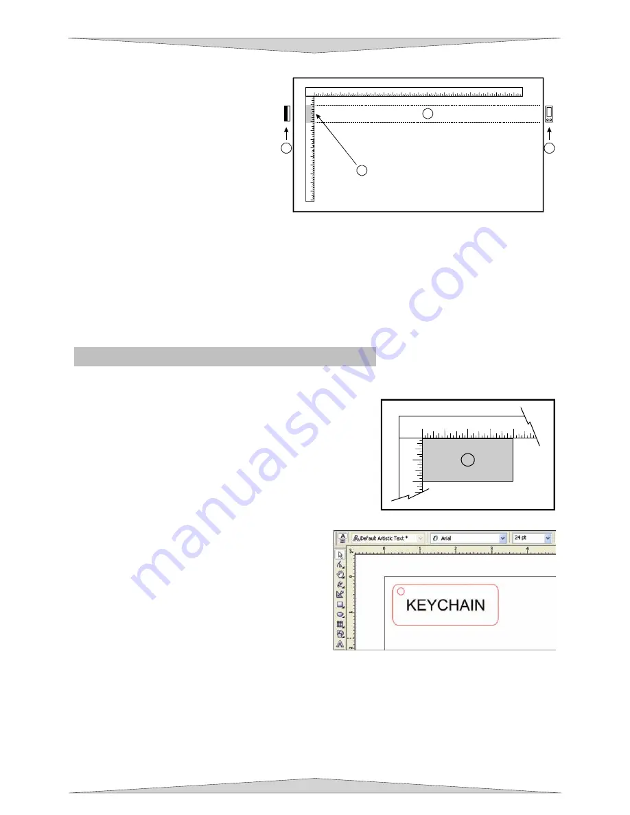
anywhere within the AUTOFOCUS zone
(1), which spans across the table where
the Y-axis ruler is indented (2). Your
material must completely obstruct the
AUTOFOCUS zone (1) in the Y-axis
direction (be at least 2 inches thick) or it
may not operate properly. To activate
AUTOFOCUS, verify that you are on the Main Menu on the Keypad screen and press and hold the
AUTOFOCUS button for one second. As soon as the process begins you can release the AUTOFOCUS
button.
The laser system’s engraving table will automatically adjust to its appropriate focusing height. Be sure
that the appropriate lens size installed is the same lens selected in the System Tab of the UCP.
Periodically check if the AUTOFOCUS method is calibrated with your focus tool. Your focus tool is your
absolute reference, so make sure that you do not lose it.
Making a Sample - Manual Control Tab
The following steps assume that CorelDraw X3 is being used as your graphics software and are using the
Manual Control Tab in the printer driver. Other graphic software programs may differ.
Step 1 – Loading and Positioning the Material
Open the top door and position the piece of wood (1) into the
upper left corner of the table, against the rulers, as the diagram
indicates. If the piece of wood is more than the example then
use the rulers to measure the size of the piece.
Step 2 – Creating the Graphic
Verify that the page size, in your graphic software,
matches the ULS printer driver’s maximum page size.
We recommend that you always leave the page size
set to the maximum for your system and position your
graphic accordingly. Create some text with a
BLACK
colored fill and
NO
outline. For example, type in the
word “KEYCHAIN”. Draw an outline box around the
text, color the outline
RED
, give the outline a thickness
of .00005 inches (or the smallest possible line width),
remove the fill color (if any), and round the edges if
desired. Now add a circle with the same
RED
outline
.00005 inches (or the smallest possible line width) and
NO
fill, for the key ring.
Position the graphic, on your computer screen, relative to size of the wood and how the piece of wood is
positioned in the engraving area.
If you are not familiar with your graphics program run a few tutorials and become familiar with the
graphics program. If tutorials were not provided you may have to learn the software on your own by
experimenting with the software.
1
2
1
0
2
3
4
I
1
2
3
4
5
6
7
8
9
10
11
12
13
14
15
16
17
18
19
20
21
22
23 24
1
2
3
4
5
6
7
8
9
10
11
12
3
2
4
I
Summary of Contents for PLS3.60
Page 8: ......
Page 20: ...SAFETY Section 1 12 ...
Page 21: ...Part 1 Initial Setup ...
Page 22: ......
Page 30: ...INSTALLATION Section 2 10 ...
Page 44: ...GRAPHICS SOFTWARE SETUP Section 3 14 ...
Page 58: ...MAKING A SAMPLE Section 5 4 ...
Page 59: ...Part 2 Laser System Essentials ...
Page 60: ......
Page 70: ...BASIC SYSTEM FEATURES Section 6 12 ...
Page 76: ...BASIC MAINTENANCE Section 7 6 ...
Page 77: ...Part 3 Accessories ...
Page 78: ......
Page 95: ...Part 4 Advanced User ...
Page 96: ......


