ACCESSORIES
Section 8-17
Calibration
1.
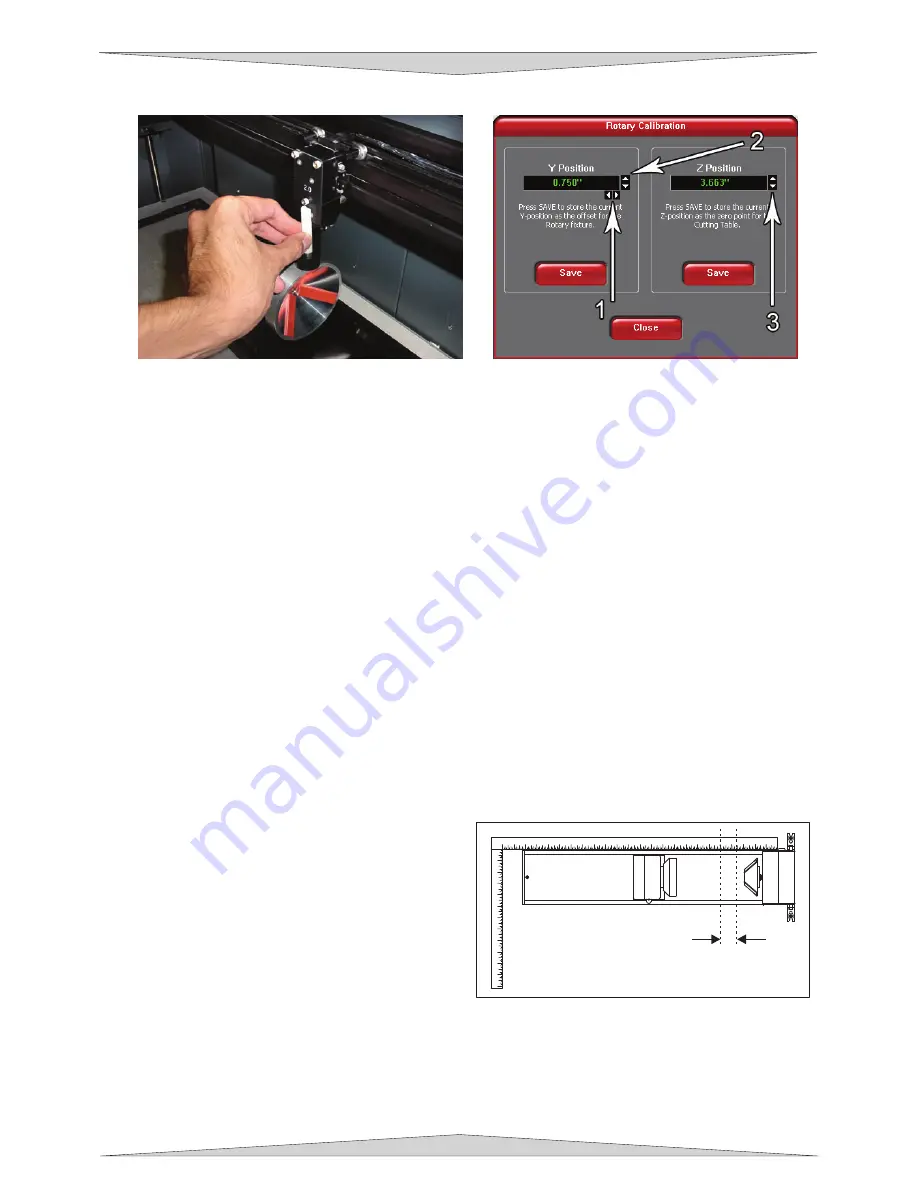
Select the System Tab and click on the CALIBRATE button in the Rotary box. After the button has
been clicked a Rotary Calibration window will appear with Y Position and Z Position boxes. Now, in
the Y Position box use the Y Axis buttons (2) to move the focus carriage back and forth. Place the
focus carriage exactly at 2.625”. Next, use the X Axis buttons (1) to move the focus carriage left and
right and place the red LED over the flat part of the concave metal fixture normally located on the left
hand side on the rotary. Now, use the Z Axis buttons (3)
or
the Z Axis Menu on your keypad
(recommended) to move the table up and down and use the Focus Tool method (Section 9-17) to
focus on top of the flat part of the concave metal fixture with the focus tool. DO NOT focus on top of
the black metal cover that is located on the left hand side of the rotary. Ignore any mention to the
MANUAL FOCUS POSITION feature and carefully focus on the top of the concave metal fixture.
2.
After focusing is complete click both SAVE buttons on the Rotary Calibration window. If asked to
overwrite an existing position accept the new value by clicking on YES. Once complete click the
CLOSE button and the focus carriage will re-home once you exit the window. Calibration is now
complete.
The rotary option on the printer driver has to be set and the rotary has to be installed properly and
calibrated in order for this accessory to function correctly.
Determining Graphic Placement
We now need to determine where we want the engraving to appear on the glass. You can use the top
ruler as a visual aid in referencing the engraving area of the glass or you can use the Red Diode Laser
and the X-Y coordinate system to precisely place the graphic in your graphics program. To be more
precise, we will use the Red Diode Laser Pointer.
To activate the Red Diode Laser Pointer, open the
top door, if it’s not already open. Using the MOTION
CONTROL buttons on the PLS keypad, position the
Focus Carriage above the glass and observe the
Red Diode Lasers position by entering the XY menu.
Stop movement where you would like the top of the
graphic (the right dotted line in the engraving area) to
begin. Look at the XY menu and read the “X”
position. Remember this number or write it down.
Ignore the “Y” position. Now, position the red dot at
the lowest point (the left dotted line in the engraving
area) on the glass where you would like the engraving to end. Remember this “X” coordinate or write it
down.
In this example our upper limit is about 20.500” and the lower limit is 19.000”. We have now set up the
glass to be engraved. Close all doors of the laser system, go to your computer, and open your graphics
software.
1
2
3
4
5
6
7
8
9
10
11
12
1
2
3
4
5
6
7
8
9
10
11
12
13
14
15
16
17
18
19
20
21
22
23
24
Summary of Contents for PLS3.60
Page 8: ......
Page 20: ...SAFETY Section 1 12 ...
Page 21: ...Part 1 Initial Setup ...
Page 22: ......
Page 30: ...INSTALLATION Section 2 10 ...
Page 44: ...GRAPHICS SOFTWARE SETUP Section 3 14 ...
Page 58: ...MAKING A SAMPLE Section 5 4 ...
Page 59: ...Part 2 Laser System Essentials ...
Page 60: ......
Page 70: ...BASIC SYSTEM FEATURES Section 6 12 ...
Page 76: ...BASIC MAINTENANCE Section 7 6 ...
Page 77: ...Part 3 Accessories ...
Page 78: ......
Page 95: ...Part 4 Advanced User ...
Page 96: ......


