Operating Manual
TYTAN premium
- page 12 -
31
58R
54
58R
31
54
58L
54
+
58R
54
58R
1
2
3
3
2
1.
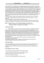
Fig. 6
Electric installation scheme
1
– Traffic indicator light (light bulb 21W); 2 – Navigation light (light bulb 5W);
3
– Brake light (light bulb 21W); 4 – Front navigation light (light bulb 10W); 5 –
connector joint; 6
– Plug-in connector socket 5N;
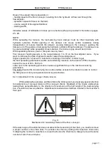
Fig. 7
Lighting system (scheme).
1
–connector cable; 2 – Plug-in connector socket; 3 – front navigation lamp; 4
– front assembly lamp; 4a – traffic indicator light; 4b – rear navigation light;
4c
– “STOP” light; 5 – retro-reflecting “triangular” device (red); 6 – retro-
reflecting device (orange), 7
– group of wires,


