


Operating Manual
TYTAN premium
- page 17 -
Dose of the spread manure depends on:
- feeding speed of the floor conveyor, resulting from the hydraulic oil flow rate through the
flow adjuster.
- spr
eader’s speed of travel on the field;
- volume weight of the applied fertilizer;
- working width;
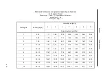
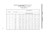
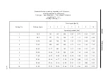
Indicative values of fertilization in tones per one hectare (t/ha) are provided in the table on pages
23 - 26.
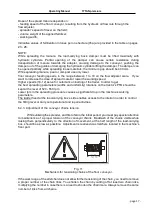
NOTE:
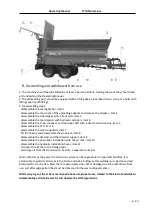
While spreading the manure, the load-
carrying box’s damper must be lifted maximally with
hydraulic cylinders. Partial opening of the damper can cause certain resistance during
transportation of manure towards the adapter, causing damage to the conveyor, pushing the
damper out of the guides or damaging the hydraulic cylinders lifting the damper. The damper can
be opened partially while spreading loose materials; the minimum gap should be 400 mm.
While spreading manure, peat or compost use only lower
floor conveyor feeding speeds, in the range between 1 to 10 on the flow adjuster scale. If you
want to increase the dose of spread material, lower the working speed.
Higher speeds (10-12) serve for automatic unloading of the trailer. In order to get
the best spreading parameters (widths and un
iformity) rotations on the tractor’s PTO should be
kept at the level of 520 - 550 rpm.
Lower rpm in the spreading procedure causes a significant drop in the machine’s working
parameters.
The ladder fixed at the load-
carrying box’s side enables access to the interior in order to control
the filling level or carry out operational and repair activities.
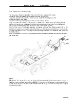
6.4.3. Adjustment of the conveyor chains tension.
While utilizing the spreader, and first of all in the initial period, you must pay special attention
to maintenance of a proper tension of the conveyor chains. Backlash of the chains visible while
raising them perpendicularly to the direction of movement, at the half length of the load-carrying
box, should be as low as possible. Adjustment is realized via stretchers
located in the machine’s
front part.
Fig. 11
Mechanism for tensioning chains of the floor conveyor.
If the work range of the stretcher does not allow further tensioning of the chain, you need to remove
a proper number of the chain links. You shorten the chain by cutting off at least two chain links,
multiplying the number in case there is a need to shorten the chain more. Always remove the same
number of links from all chains.


