Operating Manual
TYTAN premium
- page 11 -
The service brake, with rated load on the trailer, according to the Highway Code regulations, allows
to reach a delay in braking of at least 2.5 m/s2, with braking distance below 10 m. The auxiliary
parking brake holds the spreader uncoupled from the tractor on a surface inclined at up to 16%
(elevation or drop). Structure of the braking system ensures automatic activation of brakes of both
wheels in case of unexpected uncoupling of pneumatic installations of the trailer and tractor.
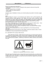
5.4. Hydraulic installation.
The hydraulic installation is coupled to the tractor with AGRIC push-in fittings. There are two
options of coupling, depending on how many pairs of hydraulic sockets the tractor is equipped with.
In a standard version there are two pairs of fittings, and in the second versions there is a possibility
to install a hydraulic divider to control particular hydraulic devices via a single pair of fittings.
Fig. 13
Hydraulic installation scheme
1
– plug valve; 2 – flow adjuster; 3 – hydraulic motor;
4
– rear cover cylinder; 5 – gear of the floor conveyor
;
6
– floor conveyor; 7
– throttle valve of the rear cover;
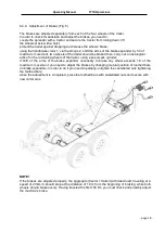
5.5. Electrical installation and lighting system.
Electrical installation of the spreader’s trailer (Fig. 6) can be powered from a 12VDC source.
The trailer’s lighting system includes all elements of lighting and signalization (Fig. 7)
provided for in the Highway Code for transportation trailers.
Terminals symbols:
31
– chassis ground; 54 – brake light; 58R – navigation
light L
– left traffic indicator; R – right traffic indicator;


