Operating Manual
TYTAN premium
- page 10
-
Mechanism adjusting tension of the chains, individually for each chain, are located in the
front part of the load-carrying body.
When the conveyor feeds forwards (towards the tractor), you must be
careful so the moved material does not damage or push the front wall of
the load-carrying body.
The floor conveyor can be controlled only during its operation.
5.3. Braking system.
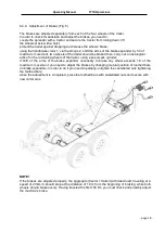
The manure spreader is equipped with a braking system, including:
-
service brake -
of a pneumatic type, controlled from the tractor’s driver cab
-
parking brake - hand, started with a crank located at the front part of the trailer Distribution
of particular elements of the braking system is presented in Fig. 5 scheme.
Fig. 5
Braking system (scheme)
1
– air tank; 2 – brake control valve; 3 – pneumatic cylinder; 4 – B2
connector (for connection
with the tractor’s pneumatic installation) ;
4a
– connectors of the dual-line installation; 5 – air duct;
6
– handbrake crank; 7 – handbrake cable.
8
– air filter; 9 – braking power adjuster; 10 – spiral hose


