T
HE
G
RAND
T
OUR
2-3
Indicators
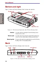
5VDC
Power connector
CAUTION: Always use the correct AC adapter to avoid the risk of fire or
damage to your Wireless Routing Center. The current rating for the
Wireless Routing Center is 2.0 amperes.
On/Off
Power switch
LAN ports 1-4
An integrated four-port 10/100BaseT switch provides four
RJ-45 ports for connection to a hub, switch or NIC-
equipped computer in your network. The LAN ports
support Auto-MDIX feature which eliminates the need for
crossover cables.
WAN port
One RJ-45 port provides connection for a Cable/ADSL
modem. The WAN port also supports Auto-MDIX, which
eliminates the need for crossover cables.
Load Default
To reset the Wireless Routing Center to factory defaults,
insert a straightened paper clip into the Load Default hole
to press the button. Keep pressing and turn the Wireless
Routing Center off and on. Wait for at least five seconds
before you release the button. Then wait for the Wireless
Routing Center to finish booting.
If you want to restore your customized settings after loading defaults, refer to the
section in Chapter 4, Web Configuration, for more informa-
tion.
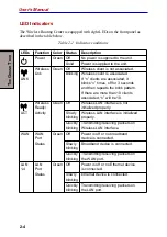
Indicators
Front Panel
The following illustration shows the front panel of the Wireless Routing Center:
Figure 2-4 The indicators
DC IN 5V
INIT
LAN
WAN
P
OWER
W
IRELESS
LAN WAN LAN: 1, 2, 3, 4

