User's Manual
T
HE
G
RAND
T
OUR
2-2
Bottom and right
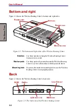
Figure 2-2 shows the Wireless Routing Center’s bottom and right sides.
Figure 2-2 The bottom and right sides of the Wireless Routing Center
Notches
Use these notches to hang the Wireless Routing Center
from screws in a wall.
Rubber pads
Use these pads to horizontal mount the Wireless Routing
Center. Lay it on a flat surface with the pad side down.
Mounting hole
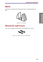
Fit pin on the stand into mounting hole to use the Wireless
Routing Center in an upright position.
Back
Figure 2-3 shows the Wireless Routing Center’s back side.
Figure 2-3 The back side of the Wireless Routing Center
N
OTCHES
M
OUNTING
HOLE
R
UBBER
PADS
R
UBBER
PADS
5VDC
L
OAD
D
EFAULT
O
N
/O
FF
WAN
PORT
LAN
PORTS
1-4

