background image

A

PPENDIX

 B

B-1

Appendix B

802.1x

Overview

The 802.1x function restricts the connection of unauthorized stations by authenti-
cating each station.

The 802.1x function has the following advantages in security and administration.

Security

The function makes authentication during station connec-
tion and permits only the station that has passed the
authentication to communicate. This function makes it
difficult for an unauthorized station to get in the network.

Administration

Because the function dynamically distributes the WEP key,
the Encryption (WEP) key does not need to be set at each
station.

 NOTES: 1. Although several authentication methods are available,

the WEP key cannot be distributed in some of those
methods.

2. If 802.1x is enabled, the following conditions apply:

a. 802.1x disabled Wireless LAN clients CANNOT commu-

nicate with LAN clients connected with the Wireless
Routing Center’s ethernet ports.

b. 802.1x enabled Wireless LAN clients CAN communicate

with LAN clients connected with the Wireless Routing
Center’s ethernet ports.

c. Wireless LAN clients CAN communicate with each other

regardless of which client’s 802.1x functions are
enabled or disabled.

Summary of Contents for WRC-1000

Page 1: ...TOSHIBA Wireless Routing Center WRC 1000 User s Manual R10UM020801 ...

Page 2: ...ting Center WRC 1000 User s Manual at the time of this manual s production However succeeding devices and manuals are subject to change without notice TOSHIBA assumes no liability for damages incurred directly or indirectly from errors omissions or discrepancies between the device and the manual Trademarks Microsoft Windows NetMeeting and Windows Messenger are registered trademarks of Microsoft Co...

Page 3: ... harmful interference to radio or television reception which can be determined by turning the equipment off and on the user is encouraged to try to correct the interference by one or more of the following measures Reorient or relocate the receiving antenna Increase the separation between the equipment and receiver Connect the equipment into an outlet on a circuit different from that to which the r...

Page 4: ...40 Irvine Boulevard Irvine California 92618 1697 Telephone 949 583 3000 EU Declaration of Conformity TOSHIBA declares that the product PA3227U PA3227E PA3227A PAWRC001 conforms to the following Standards Supplementary Information The product complies with the requirements of the Low Voltage Directive 73 23 EEC and the EMC Directive 89 336 EEC This product is carrying the CE Mark in accordance with...

Page 5: ...onsumers These standards and recommendations reflect the consensus of the scientific community and result from deliberations of panels and committees of scientists who continually review and interpret the extensive research literature In some situations or environments the use of Wireless LAN may be restricted by the proprietor of the building or responsible representatives of the organization The...

Page 6: ... is installed outdoors is subject to licensing Pour empecher que cet appareil cause du brouillage au service faisant l object d une licence il doit Etre utilise a l interieur et devrait etre place loin des fenetres afin de fournir un ecran de blindage Maximal Si le materiel ou son antenne d emission est installe a l exterieur il doit faire l objet D une license Europe EU Declaration of Conformity ...

Page 7: ...icences veuillez contacter I IBPT Deutschland License required for outdoor installations Check with reseller for procedure to follow Anmeldung im Outdoor Bereich notwendig aber nicht genehmigungspflichtig Bitte mit Händler die Vorgehensweise abstimmen France Restricted frequency band only channels 10 and 11 2457 MHz and 2462 MHz respectively may be used in France License required for every install...

Page 8: ...ation substitu tion or attachment will be the responsibility of the user CAUTION Exposure to Radio Frequency Radiation The radiated output power of the TOSHIBA Wireless Routing Center WRC 1000 is far below the FCC radio frequency exposure limits Nevertheless the TOSHIBA Wireless Routing Center WRC 1000 shall be used in such a manner that the potential for human contact during normal operation is m...

Page 9: ...o Other Radio Stations from this equipment please change promptly the frequency for use place to use or stop emitting Radio 3 Please contact TOSHIBA Direct PC if you have a problem such as interference from this equipment to Other Radio Stations 2 Indication The indication shown below appears on this equipment 2 4 DS 4 4 1 2 3 1 2 4 This equipment uses a frequency of 2 4 GHz 2 DS This equipment us...

Page 10: ...The following restrictions apply Do not disassemble or modify the device Do not install the embedded wireless module into other device Approved Countries regions for use This equipment is approved to the radio standard by the countries regions listed in the table below CAUTION Do not use this equipment except in the countries regions in the following table Australia Austria Belgium Canada Denmark ...

Page 11: ...nts 1 1 System requirements 1 1 Features 1 2 WAN port features 1 2 LAN port features 1 2 Router features 1 2 Security features 1 3 Wireless LAN features 1 3 Configuration and Management features 1 3 Chapter 2 The Grand Tour Front left and top 2 1 Bottom and right 2 2 Back 2 2 Indicators 2 3 Front Panel 2 3 LED Indicators 2 4 Stand 2 5 Screws for wall mount 2 5 AC adapter and power cord 2 6 ...

Page 12: ...7 Viewing system overview and log 4 7 Overview Configuration 4 7 Filter Log 4 8 Configuration for NAT Routing Mode 4 9 WAN Configuration for NAT Routing Mode 4 9 LAN Configuration for NAT Routing Mode 4 13 Configuration for Bridge Mode 4 16 Wireless LAN Configuration 4 18 Basic 4 18 Advanced 4 19 Wireless LAN Security 4 19 802 1x 4 20 WEP 4 20 Access Control 4 22 RADIUS Server 4 22 Filters 4 23 Sp...

Page 13: ... 1 Ethernet 5 1 Configuration window 5 1 Wireless LAN 5 3 Application problems 5 7 Forgotten password 5 8 Question 5 8 Appendixes Appendix A Default values A 1 Appendix B 802 1x B 1 Appendix C AC Power Cord and Connectors C 1 Glossary Index ...

Page 14: ...xiv ...

Page 15: ...up tells how to connect and setup your LAN devices Chapter 4 Web Configuration tells how to configure the Wireless Routing Center via Web browser Chapter 5 Troubleshooting suggests courses of action if the device doesn t seem to be working properly Appendix A lists all default settings Appendix B describes the 802 1x function Appendix C describes the power cord and connectors The Index quickly dir...

Page 16: ...ame time press C If three keys are used hold down the first two and at the same time press the third ABC When procedures require an action such as clicking an icon or entering text the icon s name or the text you are to type in is represented in the type face you see to the left Display ABC Names of Windows or icons or text generated by the computer that appears on its display screen is presented ...

Page 17: ... Address Translation NAT function your LAN is protected against outside intruders The router can also be configured to filter internal access to the Internet It is designed to provide a reliable Internet access solution for the corporate environment the small office and the home user Package contents Refer to the Quick Start Guide for the Equipment checklist If any of the items is missing contact ...

Page 18: ...mand Support PAP and CHAP Authentication DHCP Client MAC Address Cloning Settable and Changeable IP Address LAN port features Four RJ 45 LAN ports for 10 100Base TX auto sensing crossover Ethernet Switch LAN connection DHCP Server IP Address setting and changing Router features NAT Firewall Support Bridge Mode Support IP Filtering IP Forwarding Static Routing DMZ Hosting DNS Forwarding DNS Relay U...

Page 19: ...quence Spread Spectrum DSSS technology Seamless roaming within Wireless LAN infrastructure Low power consumption for wireless client via efficient power management Configuration and Management features Configurable through Web Browser via WAN LAN Software Upgradeable DHCP Server function for IP distribution to local network users NTP Manual System Clock Configuration Saving Retrieving Event Loggin...

Page 20: ...1 4 User s Manual I NTRODUCTION ...

Page 21: ... left and top Figure 2 1 shows the Wireless Routing Center s front left and top positions Figure 2 1 Front left and top of the Wireless Routing Center System The system indicators provide LEDs for monitoring the indicators Power Wireless LAN LINK Wireless LAN ACT WAN Ethernet 1 Ethernet 2 Ethernet 3 and Ethernet 4 SYSTEM INDICATORS ...

Page 22: ...crews in a wall Rubber pads Use these pads to horizontal mount the Wireless Routing Center Lay it on a flat surface with the pad side down Mounting hole Fit pin on the stand into mounting hole to use the Wireless Routing Center in an upright position Back Figure 2 3 shows the Wireless Routing Center s back side Figure 2 3 The back side of the Wireless Routing Center NOTCHES MOUNTING HOLE RUBBER PA...

Page 23: ...WAN port also supports Auto MDIX which eliminates the need for crossover cables Load Default To reset the Wireless Routing Center to factory defaults insert a straightened paper clip into the Load Default hole to press the button Keep pressing and turn the Wireless Routing Center off and on Wait for at least five seconds before you release the button Then wait for the Wireless Routing Center to fi...

Page 24: ...repeats the blink pattern If there are more than 10 clients associated n will be 10 Wireless Green Off Wireless LAN interface is not Ready initialized properly ACT Activity Slowly Wireless LAN interface is initialized blinking properly Quickly Transmitting receiving packets on blinking Wireless LAN interface WAN WAN Green Off Power is off or no broadband Port device is connected Status Slowly Broa...

Page 25: ...install the Wireless Routing Center in an upright position on a desk Figure 2 5 The stand Screws for wall mount Two screws are supplied to secure the Wireless Routing Center to a wall Figure 2 6 The two screws for wall mount Screws for wall mount ...

Page 26: ...cally adjust to any voltage from 100 to 240 volts and to a frequency of either 50 or 60 hertz enabling you to use the Wireless Routing Center in almost any country region CAUTION Always use the correct AC adapter to avoid the risk of fire or damage to your Wireless Routing Center The current rating for the Wireless Routing Center is 2 0 amperes Figure 2 7 The AC adapter and power cord ...

Page 27: ...onnect cables The figure below shows an example of connections in a LAN and a LAN connec tion to the Internet Internet Internet Service Provider Cable ADSL Modem Wireless Routing Center Ethernet Desktop PC Desktop PC Wireless LAN Client PC Wireless LAN Client PC Wireless LAN Client PC Server Home Office Figure 3 1 Network connections ...

Page 28: ...people may walk on the cables Also keep it away from direct sunshine or heat sources 3 Place the device on a flat and stable stand Vertical mounting To install the Wireless Routing Center upright on a desk use the stand provided as an accessory 1 Align the peg on the stand with the hole in the Wireless Routing Center and fit the Wireless Routing Center into the stand Figure 3 2 Installing the Wire...

Page 29: ...outing Center upright Figure 3 3 The Wireless Routing Center s upright position in a stand Horizontal mounting Four rubber pads protect the back of the Wireless Routing Center Lay it on a flat surface with the pad side down Mounting ...

Page 30: ...llow the steps below to connect the AC adapter 1 Connect the power cord to the AC adapter 2 Connect the AC adapter to the DC IN jack on the back of the Wireless Routing Center 3 Connect the power cord to an electrical outlet 100 to 240 VAC CAUTION Use the adapter supplied with the Wireless Routing Center Connecting the wrong adapter could damage the Wireless Routing Center TOSHIBA assumes no liabi...

Page 31: ...ardware make sure to power off your Ethernet device Cable ADSL modem and Wireless Routing Center Then follow the steps below to connect the related devices CAUTION The computer must be configured properly before connect ing to a LAN Logging onto a LAN using the computer s default setting could cause a malfunction in LAN operation Check with your LAN administrator regarding set up procedures Connec...

Page 32: ...the LAN port 2 Connecting Cable ADSL modem to the WAN port Connect the Ethernet cable attaching to your Cable ADSL modem to the WAN port of your Wireless Routing Center Figure 3 7 Connecting the WAN port 3 Connecting the power adapter Connect the single DC output connector of the power adapter to the power jack on the side of the Wireless Routing Center Then connect the supplied power cord to the ...

Page 33: ...ion describes how to configure your computer to be a DHCP client for initial connection to the Wireless Routing Center If you have modified the Wireless Routing Center s network setting your LAN Wireless LAN clients should make appropriate changes in order to make a successful connection Setting up Ethernet client To access the Wireless Routing Center via Ethernet make sure your computer is equipp...

Page 34: ...owing steps help you verify that your network adapter gets an IP address within the DHCP IP pool range 192 168 10 100 192 168 10 150 by default of the Wireless Routing Center If not you may need to renew the IP information 1 Click Run from the Start menu to open the Run dialog box 2 Type cmd in the dialog box and then click OK 3 At the prompt type ipconfig to see the IP information from DHCP serve...

Page 35: ...click Properties 4 Enable Obtain an IP address automatically and then click OK Figure 3 9 Obtain an IP address automatically Checking Renew IP Address under Windows 2000 To check if your network adapter gets an IP address within the DHCP IP pool range 192 168 10 100 192 168 10 150 by default of the Wireless Routing Center follow the related description under the Windows XP section The proce dures ...

Page 36: ...e Configuration window highlight TCP IP protocol for your NIC and click Properties 4 In the IP Address window select Obtain an IP address automati cally Then click OK Figure 3 10 Obtain an IP address automatically 5 If your network settings is changed you will be prompted with the System Settings Change dialog box Click Yes to restart your computer ...

Page 37: ...Release and then Renew to get a new IP address Figure 3 11 Specify an IP Configuration Setting up Wireless client You can also choose to access the Wireless Routing Center via a wireless client whether for configuration purposes or sharing network resources and an Internet connection To get your wireless client connected to the Wireless Routing Center verify the following 1 Make sure your computer...

Page 38: ...and open a DOS window and ping the IP address of the Wireless Routing Center at the DOS prompt For example ping 192 168 10 1 If the following response occurs Reply from 192 168 10 1 bytes 32 time 100ms TTL 255 Then the connection between the Wireless Routing Center and the network is OK If you get a failed ping with the response of Request time out Then the connection has not been made Verify your...

Page 39: ...Utility CD ROM to open the Wireless Routing Center s Web Configuration page NOTES 1 If data is being transmitted while you are changing settings transmission will be interrupted when you click Apply 2 The DHCP server function is enabled before the Wireless Routing Center is shipped If the LAN has other DHCP servers the DHCP server function of the Wireless Routing Center must be disabled 3 You will...

Page 40: ...outing Center you want to change Your Web browser will start and display that Wireless Routing Center s Web Confirmation Page NOTE If you know the IP address of the Wireless Routing Center you want to set you can enter http in your Web browser and go directly to the Web Confirmation Page specifies the IP address of the Wireless Routing Center The default value is 192 168 10 1 Figure 4 1 Web Browse...

Page 41: ...eless Routing Center 1 A dialog box will be displayed asking you if you want to search for Wireless Routing Centers Figure 4 3 Confirmation window 2 If you click No WRC Finder will do nothing At this point you can still continue by clicking Search 3 If you click Yes the Wireless Routing Center search will begin In about five seconds a list of Wireless Routing Centers will be displayed ...

Page 42: ...hannel that is being used Figure 4 4 WRC information 5 If no Wireless Routing Center is found the Confirm dialog box is displayed again 3 Open the Web Configuration page Double click the Wireless Routing Center you want to set The Web browser will start and display the selected Wireless Routing Center s Web Configura tion Page A Password input window will also be displayed If the Password input wi...

Page 43: ...rname admin and enter the default password of password Figure 4 5 Password window After you login the Overview Configuration page of the Wireless Routing Center will be displayed From this point on the Wireless Routing Center will act as a Web server sending HTML pages forms on your request You can click the menu options at the left side to start your configuration task ...

Page 44: ...ure 4 6 Configuration window When you make settings with the Web configuration utility fields related to a selected option will be displayed to avoid conflicting setting The utility also displays an error message if you enter an invalid value ...

Page 45: ...ge which shows the basic information of your Wireless Routing Center including the system WAN LAN interface and Wireless LAN interface information In addition to the general information this page contains the followingelements Update button Click the Update button on the top to update the overall status Language Selection Lets you select the Web browser s encoding language English or Japanese WAN ...

Page 46: ...FIGURATION Figure 4 8 Overview Configuration Filter Log Iffilterfeatureisenabled youcanclicktheLoglinkinStatusmenutodisplaythefilter activity log See Viewing Filter Log for more information on log category Figure 4 9 Activity Log ...

Page 47: ...he WAN port of the Wireless Routing Center will be assigned a public IP address from your ISP s server Manual Config If your ISP assigns you a fixed IP address you should select this option and manually enter the IP information provided by your ISP The configuration items displayed depend on your connection type Ask your ISP which option applies to you and obtain the information you need for corre...

Page 48: ...eed of asking your ISP to change the registered MAC address You can still use the same IP you were given for the router s WAN port 4 In the Host Name field you can supply a host name for the Wireless Routing Center if this is required by your ISP Some ISPs only respond to a DHCP request with a valid Host Name If a host name is not necessary for your ISP leave it blank Part 2 Configuring protocol s...

Page 49: ...he ISP to prevent the connection from being terminated by the ISP Connect on Demand If enabled the router will trigger a PPP session for connection to the Internet if any client computer on your LAN sends a request for Internet access However the router automatically disconnects the PPP session after the WAN connection has been idle for the amount of time specified in the Max Idle Time box If your...

Page 50: ... gateway of the router is the IP that the Wireless Routing Center first contacts to communicate with the Internet The default is 0 0 0 0 DNS Servers Specifies the IP address of the Domain Name Server Your LAN side DHCP clients use the DNS to map a domain name to its corresponding IP address and vice versa Up to three DNS servers are allowed WINS Servers Optional for Windows Internet Names Service ...

Page 51: ...N interface 1 In the Manual Config IP Address Subnet Mask field enter the IP address and subnet mask for the LAN port The default LAN port IP address is 192 168 10 1 and the subnet mask is 255 255 255 0 Note that if you change the private IP address and apply the changes the computer from which you configure the router will lose commu nication to the router To reconnect you will need to renew the ...

Page 52: ...ady has a DHCP server do not enable this function DHCP server is enabled by default NOTE Only one DHCP server can run on one LAN If you decide to enable DHCP on this router remember to disable the DHCP function of the other device If you disable DHCP no further configuration is required for the Wireless Routing Center Click Apply to submit your changes If you enable DHCP proceed to the next step N...

Page 53: ...ss from this pool and lease it to the device for a specified amount of time Figure 4 13 LAN Configuration in Router Mode Viewing Current DHCP Assignments When the DHCP server function is enabled for your LAN the Wireless Routing Center keeps a record of any computer either Ethernet or Wireless node that has leased an IP from the specified IP pool The DHCP lease table is displayed under Overview LA...

Page 54: ...mmit the changes Figure 4 15 Enabling Bridging Part 2 LAN configuration In the General Protocol field select Manual Config or DHCP Client as required DHCP Client Select this option if your network already has a DHCP server that assigns IP to this bridge If enabled no further configuration is needed since the DHCP server will pass the required IP information Click Apply to submit your changes NOTE ...

Page 55: ...dress its subnet mask and default gateway in IP Address Subnet Mask Default Gateway fields NOTE To reconnect after committing this setting you will need to make sure the computer uses an IP address in the same subnet as the manually entered IP Figure 4 17 Bridge Mode Manual Config Configuration for Bridge Mode ...

Page 56: ...eless settings to prevent unauthorized association NOTE One Wireless Routing Center can accommodate multiple computers However optimal LAN operation can be maintained with up to 10 computers Figure 4 18 Wireless LAN Configuration Basic Access Point Name The name used to identify the Access Point SSID Network Name Service Set ID It uniquely identifies the logical network domain name of your Wireles...

Page 57: ...s RTS CTS mechanism Packets that exceed the specified RTS threshold trigger the RTS CTS mechanism Fragmentation Threshold It determines whether packets will be fragmented and at what size On an 802 11 wireless LAN packets that exceed the fragmentation threshold are fragmented into smaller units suitable for the circuit size On the other hand packets smaller than the wireless station s should be us...

Page 58: ... will appear when the 802 1x function is used WEP WEP Mode WEP Wired Equivalent Privacy is an authentication algorithm that encrypts your data and protects your Wireless LAN against eavesdropping WEP is disabled by default If you want to protect your data when it is transferred from one station to another you should enable this security option For security concerns we strongly recommend that you e...

Page 59: ...f WEP is disabled the Authentication Mode is automatically set to Open WEP Key Type and WEP Keys For flexibility you can enter the WEP keys in either ASCII or Hexadecimal format Select a format and then enter the key values in the WEP keys 1 4 fields All four fields need to be entered Note that when using Hexadecimal format only digits 0 9 and letters A F a f are allowed Valid key length for each ...

Page 60: ...ddress matches an address in the Allow List To enable this function select Enable option and enter the MAC Address of the Wireless LAN card in a Wireless LAN station to be allowed access to the Wireless Routing Center A MAC address must be entered in 12 digits of hexadecimal punctuated by a colon every 2 digits MAC addresses must be separated by a comma Spaces tabs and line feed are ignored Exampl...

Page 61: ...t issue and system administrators may need to build access controls to protect the network Filters serve as a basic security measure for your network When the filter function is enabled the Wireless Routing Center inspects all data packets received from the LAN and determines if packets are allowed to pass through the WAN port Whether a packet is allowed to pass through depends on whether it match...

Page 62: ...ingle IP address Up to 5 entries are allowed TCP Port Filters Allows or prohibits LAN computers in the specified IP range to use TCP based service in the specified port range through the WAN port You may enter the same address in both IP Start and IP End fields to define a single IP address Up to 12 entries are allowed For example to allow or prohibit a local computer 192 168 10 210 to use FTP ser...

Page 63: ...All packets can pass through the WAN port Defaults If any filter is enabled only the packets matching the specified rule are blocked other packets can pass through the WAN port When Filter Type is Listed Pass If all filters are disabled No filter rule is specified to allow any packet to pass All packets are blocked If any filter is enabled Only the packets matching the specified rule can pass othe...

Page 64: ...rvers on your local network By default forwarding entry is empty and any external access to your LAN is blocked Once you define a forwarding entry incoming packets identified by port number that match your Forwarding criteria will be forwarded to the port range of the specified local computer Otherwise packets are blocked Forwarding protects your network from hazardous packets However if you desig...

Page 65: ...owed according to your forwarding settings For example if you do not specify FTP virtual service in the Forwarding table incoming FTP requests identified by port number in packets are blocked or otherwise sent to the DMZ host if specified On the other hand if an FTP forward ing entry has been set up the FTP requests will be forwarded to the specified computer NOTE If you set multiple forwarding en...

Page 66: ...eed to shift the incoming HTTP request destined for local web server to port 8080 of your Web server the forwarding entry may look like this Start End IP Address Start End 8080 8080 192 168 10 4 8080 8080 With the settings above an external host trying to access your local Web server should use an address like this http 204 71 200 143 i e the WAN IP address 8080 If you do not enter the suffix 8080...

Page 67: ...f the destination IP address Gateway The IP address of the gateway where data packets are to be sent Cost Hop Count The number of hops number of relay routers to go through Interface The interface through which data is forwarded to the next hop For example you want to route the packet destined to the sub network 192 168 100 0 255 255 255 0 to the next hop 192 168 10 10 and there are 3 routers the ...

Page 68: ...tion 2 Manual setting 1 In the Set by field enable the Manual Setup option 2 Type the date and time in their respective fields NOTE Normally the Administration Configuration Page displays the set values It is a good idea to check these values periodically to make sure they have not been changed To verify the current time refer to the Overview Page u Management Setup Username and Password For admin...

Page 69: ...red If WAN Management is enabled using port 80 your publicly accessible Web server if any on the LAN side should use a non 80 HTTP port You will need to use the Forwarding feature to shift external HTTP requests to the non 80 port number used by the Web server on the LAN side WAN Port Ping Reply Available only in NAT Routing Mode If available this setting determines if an external host will get a ...

Page 70: ...the TFTP server and that of the Wireless Routing Center are in the same subnet Figure 4 24 Administration Configuration System Configuration u Firmware Upgrade This option allows you to upgrade the Wireless Routing Center with new firmware After upgrading your customized configurations will still be effective Upgrading does not revert to the default settings To upgrade download the firmware file t...

Page 71: ...ault button on the back panel or via the Restore button in this group you can restore your last customized settings by clicking the Retrieve button Restore Factory Defaults To restore factory defaults click the Restore button and then wait for a few minutes as the utility prompts You will return to the System configuration page when the process is complete This feature lets you remotely reset the ...

Page 72: ...4 34 User s Manual W EB C ONFIGURATION ...

Page 73: ... Setup and reconnect the cable Cause The cable is inappropriate Remedy Refer to the Setting up the Ethernet Wireless LAN client section in Chapter 3 Setup and make sure you are using the proper cable Configuration window The Configuration window does not open even if the IP address of the Wireless Routing Center is entered in the address box of the browser Cause 1 The local IP address of the Wirel...

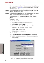
Page 74: ...as the local IP address of the Wireless Routing Center To confirm the local IP address of the computer follow the steps below Windows XP 2000 1 Click Start and Run 2 Enter cmd to open the Command Prompt window 3 Enter ipconfig and press Enter 4 Check the values for the IP address and subnet mask IP address 192 168 10 100 192 168 10 150 Subnet Mask 255 255 255 0 Default Gateway 192 168 10 1 Windows...

Page 75: ... Account enter those values If you have forgotten them reset to the defaults Refer to the Load Default item in Chapter 2 The Grand Tour Wireless LAN There is no communication between a Wireless LAN station and other computers Cause 1 The functions of Wireless LAN stations have not been correctly installed Remedy Read the manual for your Wireless LAN PC card and check that the driver has been insta...

Page 76: ... Control is enabled Cause 3 TCP IP has not been set or has been improperly set at one or more of the computers Remedy Confirm that the IP address has been correctly set Windows XP 1 Click Start point to All Programs Accessories and click Command Prompt to open the Command Prompt window 2 Enter ipconfig and press Enter 3 Check the values for the IP address and subnet mask IP address 192 168 10 100 ...

Page 77: ...up the Ethernet Wireless LAN client section in Chapter 3 Setup for more information Windows 98 Me 1 Click Start and Run then enter winipcfg in the input box 2 Check the values for the IP address and subnet mask in the winipcfg dialog box In an ordinary small scale LAN environment the subnet mask is set to 255 255 255 0 In this case confirm that the first three sets of digits of the IP address of t...

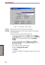
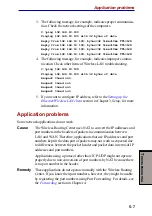
Page 78: ...ing settings 1 To open the command prompt click Start point to Programs and Accessories If you are using Window Me click MS DOS Prompt If you are using Window 2000 click Command Prompt If you are using Windows XP click Start point to All Pro grams Accessories and click Command Prompt to open the Command Prompt 2 Enter a ping command and the IP address Example C ping 192 168 10 100 Press Enter To c...

Page 79: ...rnet Wireless LAN client section in Chapter 3 Setup for more information Application problems Some network applications do not work Cause The Wireless Routing Center uses NAT to convert the IP addresses and port numbers in the headers of packets in communication between LAN and WAN Therefore applications that use IP addresses and port numbers kept in the data part of packets may not work as expect...

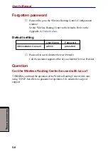
Page 80: ...lues Default setting User Name Password Administrator Account admin password Password to access Internet Service Provider Call the customer support office of your Internet Service Provider Question Can the Wireless Routing Center be used with Linux TOSHIBA confirmed the operation of the Wireless Routing Center with Linux using TCP IP but offers no guarantee of operation It is outside the scope of ...

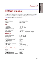
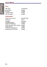
Page 81: ...Client LAN IPAddress 192 168 10 1 Subnet Mask 255 255 255 0 DHCPServerService enable DHCPLeaseTime 72hours IP Pool Range 192 168 10 100 192 168 10 150 WirelessLAN Access Point Name WRC 1000_AP NetworkName WRC_Network ChannelID 10 Do not broadcast SSID disable BeaconInterval 100 RTSThreshold 2346 FragmentationThreshold 2346 Basic Rate 1 and 2 Mbps SupportedRate 1 2 5 5 and 11 Mbps Wireless LAN Secu...

Page 82: ...ble TCP Port Filters disable UDP Port Filters disable Administration System Clock set by ManualSetup Username admin Password password WANManagement disable WAN Port Ping Reply disable WRC Finder Function Via WAN disable UPnP Function enable NetBIOSCommunication disable ReportLogtoTFTPServer disable ...

Page 83: ...e the function dynamically distributes the WEP key the Encryption WEP key does not need to be set at each station NOTES 1 Although several authentication methods are available the WEP key cannot be distributed in some of those methods 2 If 802 1x is enabled the following conditions apply a 802 1x disabled Wireless LAN clients CANNOT commu nicate with LAN clients connected with the Wireless Routing...

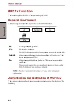
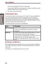
Page 84: ...the station side RADIUS Abbreviation of Remote Authentication Dial In User Service This server authenticates STAs CA Abbreviation of Certificate Authority This sever issues a digital certificate This server is required to use an authentication type that is called EAP TLS SmartCardorothercertificate NOTE The above terms abbreviations are used in the subsequent explanations Authentication and Distri...

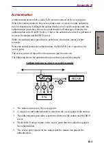
Page 85: ...e station cannot join the network When the station passes the authentication the RADIUS server reports to the access point The access point will then allow the station to join the network The following shows the authentication procedure successful example Authenticationprocedure successfulexample RADIUS STA AP 4 3 5 2 1 6 1 The station connects to the access point 2 A request to start authenticati...

Page 86: ...uted depends on the authentication type The following lists the typical types of authentication Name Description MD5 Challenge Authentication method using the user name and password In this type of authentication the WEP key cannot be distributed EAP TLS Authentication method using a digital certificate It may be represented by Smart Card or other certificate To use this type of authentication the...

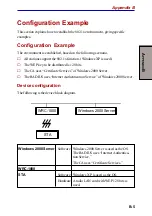
Page 87: ...ed is 128 bits The CA uses Certificate Services of Windows 2000 Server The RADIUS uses Internet Authentication Service of Windows 2000 Server Device configuration The following is the device block diagram WRC 1000 STA Windows 2000 Server Windows 2000 Server Software Windows 2000 Server is used as the OS The RADIUS uses Internet Authentica tionService The CA uses Certificate Services WRC 1000 STA S...

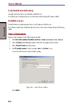
Page 88: ... details on Internet Authentication Service refer to the online Help of Windows 2000 Step 1 Client setting Make client settings in the following procedure 1 Start Internet authentication service in Administrative Tools 2 Select Client in the Tree window and click the right mouse button 3 Select New Client from the menu 4 Set Friendly name In this example WRC 1000AP is set Leave the other items in ...

Page 89: ...communication between the access point and the RADIUS server In this example my shared secret is set Leave the other items in the default setting Figure B 2 Add RADIUS Client window ClickFinish Step 2 Setting Remote Access Policies 1 Select Remote Access Policies in the Tree window and click the right mouse button 2 Select New Remote Access Policy from the menu Appendix B ...

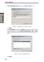
Page 90: ...Add Remote Access Policy window ClickNext 4 Add a Conditions by pressing the Add button This example defines that this policy should be used when Client Friendly Name is WRC 1000AP Various conditions are available For details refer to Windows 2000 online Help Figure B 4 Add a Conditions window ClickNext ...

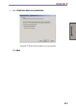
Page 91: ...A PPENDIX B B 9 5 SelectGrant remote access permission Figure B 5 Select Grant remote access permission ClickNext Appendix B ...

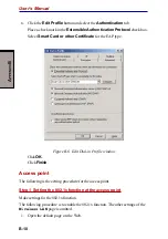
Page 92: ...rtificate for the EAP type Figure B 6 Edit Dial in Profile window ClickOK ClickFinish Access point The following is the setting procedure for the access point Step 1 Setting the 802 1x function at the access point Make settings for the 802 1x function The following procedure is to enable the 802 1x function The other settings of the Wireless LAN page is omitted 1 Open the default page on the Web ...

Page 93: ...value in the IP Address field Enter the IP address of the RADIUS server Inthisexample set192 168 10 10 Set a value in the Port field In this example set1812 Set a value in the Shared Secret field Shared secret is a password for communication between the access point and the RADIUS server In this example set my shared secret The characters you enter in this field will be displayed as Set a value in...

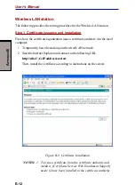
Page 94: ...e local computer 1 Temporarily have the station join the wired LAN network 2 Start the Internet Explorer and connect to the following URL http theCA sIPaddress certsrv Then install the certificate according to instructions on the screen Figure B 8 Certificate Installation NOTES 1 To issue a certificate from the certificate authority and install it Certificate Service Web Enrollment Support needs t...

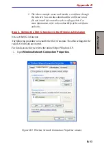
Page 95: ...the online Help of the certificate authority Step 2 Setting the 802 1x function in the Wireless LAN station Next setthe802 1xfunction The following procedure is to enable the 802 1x function The other settings for the radioLANnetworkareomitted For details on each item refer to the online Help of Windows XP 1 Open Wireless Network Connection Properties Figure B 9 Wireless Network Connection Propert...

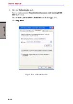
Page 96: ... Manual 2 Select the Authentication tab Placeacheckmarkinthe Enable network access control using IEEE 802 1xcheckbox Select Smart Card or other Certificate in the EAP type field ClickProperties Figure B 10 Authentication tab ...

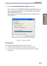
Page 97: ... Trusted root certifi cate authority combo box In this example select the certificate authority which was installed in Win dows2000Server Figure B 11 Properties window Check items Check whether authentication ended successfully as follows Check the Windows 2000 Server system log for source name IAS Check the status of the radio LAN adaptor on the Windows XP network control panel Appendix B ...

Page 98: ...A PPENDIX B B 16 User s Manual ...

Page 99: ...5amperes Voltagerating 125or250VAC depending on country region s power standards Certificationagencies U S and Canada UL listed and CSA certified No 18 AWG Type SVT or SPT 2 two conductor Europe Austria OVE Italy IMQ Belgium CEBEC The Netherlands KEMA France UTE Germany VDE UnitedKingdom BSI Australia AS Japan DENANHO InEurope powercordsmustbeVDEtype H05VVH2 Fandtwoconductor For the United States ...

Page 100: ...d Canada United Kingdom Australia Europe BS approved UL approved CSA approved AS approved Approved by the appropriateagency The following illustrations show the plug shapes for the U S A and Canada the United Kingdom Australia and Europe ...

Page 101: ...ete packet Therefore stations on either side of a bridge may be transmitting simulta neously without causing collisions C channel The channel is the radio frequency used to communicate on a wireless LAN Wireless LANs use the frequency band of 2 4 GHz divided into two or more subchannels Usable chan nels are restricted by the regulations in each country Channels 1 to 11 are usable in the United Sta...

Page 102: ...ng Ensures that only computers that are registered with the device will be allowed access either to the Internet or to a wired LAN E encryption The device allows use of data encryption compliant with the IEEE802 11standardWEP Wired EquivalentPrivacy and128bitWEP Data encryption protects your data from external access ESSID Seenetworkname G globalIPaddress AglobalIPaddress is used to identify a com...

Page 103: ... a protocol to authenticate computers communicating with each other in a network such as a personal computer connected by phone line to a server PPPoE Point to PointProtocolover Ethernet protocol A set of rules used for trans mittingdata Proxy server A proxy server acts as a connection point between a network and the Internet and serves as an agent for computers in the network Proxy server can ref...

Page 104: ...agramProtocolispartof the TCP IP suite of protocols UDP is a connectionless protocol for data trans mission that does not acknowledge whether packets are received or not It enables faster performance but there is no assurance of an accurate transmis sion UPnP UniversalPlugandPlayisde signed to support zero configuration It allows Windows XP to automatically configure the Router for various Inter n...

Page 105: ... 2 2 Defaults load default switch 2 2 restore 4 33 values A 1 DHCP 1 2 E Encryption 4 21 Ethernet features 1 1 F Filters log 4 26 rules 4 23 types 4 24 Finder See WRC finder Firmware upgrade 4 32 Forwarding 4 26 I Indicators icons 2 3 LED table 2 4 location 2 1 Initialize switch See Defaults load default switch L LAN client set up Ethernet 3 7 wireless 3 11 configuration 3 7 connections 3 5 DHCP s...

Page 106: ...ures list 1 3 Wireless LAN 4 19 802 1x 4 20 access control 4 22 RADIUS Server 4 22 WEP 4 20 Stand 2 5 Startup 3 7 System configuration 4 32 firmware upgrade 4 32 user configurations 4 33 System requirements 1 1 T Troubleshooting 5 1 application problems 5 7 configuration window 5 1 Ethernet 5 1 forgotten password 5 8 Linux 5 8 power 5 1 Wireless LAN 5 3 U User name 4 11 W WAN connection 3 5 port 2...

Reviews: