


4-8
Figure 4-6 Removing the PCMCIA Card from Slot 2
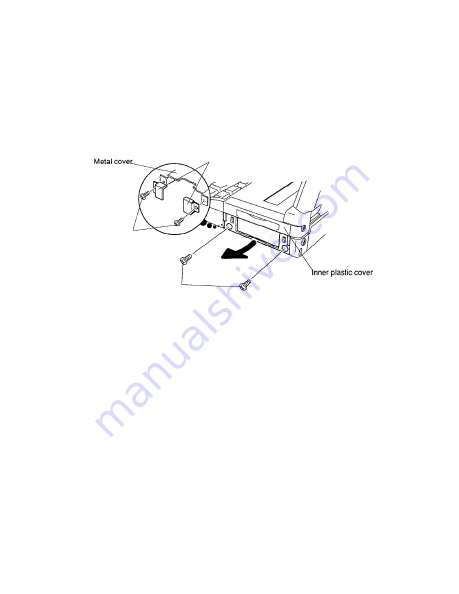
6. Remove the two M2.5x4 silver screws on the slot’s inner plastic cover. Grasp the bottom
of the inner plastic cover and pull it in the arrow’s direction to remove (Figure 4-7).
7. If optional metal retaining brackets are installed, remove the two M2.5x4 silver screws
securing them to the metal cover (Figure 4-7).
8. Grasp the card in card slot 1, and pull it straight out (skip step 9).
9. Remove the two M2.5x4 silver screws on the slot’s inner plastic cover. Grasp the bottom
of the inner plastic cover and pull it in the arrow’s direction to remove (Figure 4-7).
Figure 4-7 Removing the Inner Plastic PCMCIA Cover
Installing the Optional PCMCIA Card(s) & Assembling the Slot
To install optional PCMCIA card(s) in the computer or assemble the slot, follow the steps below
and refer to Figures 4-5 through 4-7:
1. To access the PCMCIA card slot 1, follow Steps 1 through 7 in the above section on remov-
ing the optional PCMCIA card.
2. To install a PCMCIA card in slot 1, carefully insert the card, making sure the card is right
side up and the contact surface is inserted first. If necessary, replace the optional metal
retaining brackets and secure them with two M2.5x4 silver screws (Figure 4-7).
3. Snap on the inner plastic cover and secure it with two M2.5x4 silver screws (Figure 4-7).
4. To install a PCMCIA card into slot 2 (T4600/C only), unlatch the top half of the inner
plastic cover and swivel it downward. Insert the card making sure the card is right side up
and the contact surface is inserted first. Gently push the card until it firmly connects
(Figure 4-6).
5. Carefully snap on the outer plastic cover (Figure 4-5).
M2.5x4 silver screws
M2.5x4
silver screws
Metal retaining brackets
Summary of Contents for T-Series T4500
Page 4: ...1 4 Figure 1 3 T4600 T4600C System Unit Configuration ...
Page 24: ...1 24 ...
Page 169: ...4 54 ...
Page 175: ...B 2 B G K N O R P Q C S I D H F T C A M E J Figure B 2 T4500 T4500C System PCB FSH4S1 Back L ...
Page 177: ...B 4 B 2 T4600 T4600C System Board Figure B 3 T4600 T4600C System PCB FSH1S1 Front ...
Page 178: ...B 5 Figure B 4 T4600 T4600C System PCB FSH1S1 Back ...
Page 196: ...D 1 APPENDIX D ASCII Character Codes Table D 1 ASCII Character Codes ...


