No.
Part
Work procedure
Remarks
Inverter
assembly
(continued)
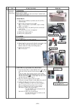
2. Attachment
1) Carry out installation by following reverse procedure in
the detachment 1) to 7).
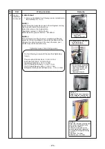
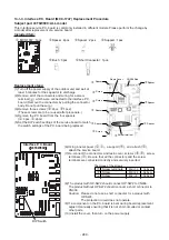
NOTE 1
Apply thickly the heat sink grease to the refrigerant cooling
heat sink and install the inverter box.
Return the wires to the original state.
(Application amount : 100 to 200
m)
Heat dissipation grease (Part No. : 43167044)
NOTE 2
If the refrigerant cooling heat sink is twisted significantly,
adjust it so that it is parallel to the contact surface with the
refrigerant cooling heat sink of the box; otherwise, poor
contact may cause operation stop.
4
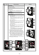
Tightening torque of each fixing screws.
Fix the following screws with the specified tightening
torque.
Power supply terminal block : 2.5 to 3.0 N•m
Earth termianl block : 5.5 to 6.6 N•m
Signal termianl block : 1.2 to 1.4 N•m
INV P.C.boardComp.fixing : 1.9 to 2.1 N•m
INV P.C.boardReactor fixing : 1.9 to 2.1N•m
Refrigerant cooling heat sink fixed screw : 1.4 to 1.5 N•m
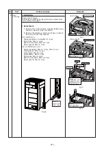
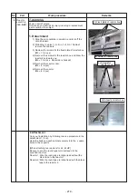
5) Fixing screws for the
box (6 pcs).
Equal to 8-24HP
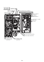
7) Lift the inverter assembly
lightly to disengage the
upper hook (2 pcs), and
remove the inverter
assembly.
Equal to 8-24HP
6) Disengage the fixing hook
at the lower right.
ޓޓ
(Equal to 8-24HP)
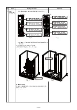
(NOTE1)
Apply the the heat sink grease
to the refrigerant cooling heat
sink and install the inverter box.
(NOTE 2)
Adjust the refrigerant cooling heat
sink so that it is parallel to the
heat sink on the box.
Follow the size below for the
space between the waterproof
cover and the refrigerant cooling
heat sink
Top space : 4 to 6mm,
Bottom space : 4 to 6mm
- 276 -
Summary of Contents for MMY-MUP0801HT7JP
Page 309: ......

