230
6
F
2
S
0
8
3
4
Note
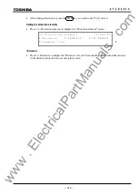
: The switch [T. TEST] must be used only when all the terminals are out-of-service.
The [D. TEST] is used to test the relay models with an optical interface. Setting the [D. test] to "1"
(= On) enables loop-back tests under the direct connection of the communication circuit.
IECTST
•
Enter 1(=On) for [IECTST] to transmit ‘test mode’ to the control system by IEC60870-5-103
communication when testing the local relay, and press the ENTER key.
•
Press
the END key to return to the "Test" screen.
THMRST
The switch [THMRST] is used to perform the thermal overload element test because the resetting
time is in the order of minutes. The thermal overload element is instantaneously reset when the
[THMRST] is ON.
•
Enter 1(=On) for testing the thermal overload element, and press the ENTER key.
•
Press
the END key to return to the "Test" screen.
UVTEST
•
Enter 0(=Off) or 1(=On) to set disable/enable the UV blocking (UVBLK) and press the
EN TER
key.
•
Press
the
END
key to return to the "Test" screen.
COM
∗
and SCOM
∗
In the integral digital communication, it is possible to forcibly send communication data [COM1]
to [COM14] and [SCOM1] to [SCOM4] for testing. If testing, a desired communication data is set
to ”ON” and press 1(=Telecomm channel test) on the "Manual test" screen.
4.2.7.2 Manual Testing
When the external communication is applied, the automatic test of the telecommunication circuit
can be performed manually by key operations. The manual test performed here is also counted as
the count displayed in Section 4.2.3.4.
•
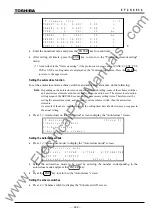
Press 2 (= Manual test) on the "Test" screen to display the "Manual test" screen.
/ 2
M a n u a l t e s t
1 = T e l e c o m m c h a n n e l
t e s t
P r e s s n u m b e r
t o
s t a r t
t e s t .
Performing the signal channel test
•
Press 1 on the "Manual test" screen to start the test. The display shown below appears.
/ 2
M a n u a l
t e s t
T e l e c o m m
c h a n n e l
t e s t i n g . . .
If the test is completed normally, the display shown below appears on the LCD for 5 seconds and
then changes to the "Manual test" screen.
www
. ElectricalPartManuals
. com
Summary of Contents for GRZ100-211B
Page 323: ... 322 6 F 2 S 0 8 3 4 w w w E l e c t r i c a l P a r t M a n u a l s c o m ...
Page 343: ... 342 6 F 2 S 0 8 3 4 w w w E l e c t r i c a l P a r t M a n u a l s c o m ...
Page 383: ... 382 6 F 2 S 0 8 3 4 w w w E l e c t r i c a l P a r t M a n u a l s c o m ...
Page 395: ... 394 6 F 2 S 0 8 3 4 w w w E l e c t r i c a l P a r t M a n u a l s c o m ...
Page 411: ... 410 6 F 2 S 0 8 3 4 w w w E l e c t r i c a l P a r t M a n u a l s c o m ...
Page 423: ... 422 6 F 2 S 0 8 3 4 w w w E l e c t r i c a l P a r t M a n u a l s c o m ...
Page 443: ... 442 6 F 2 S 0 8 3 4 w w w E l e c t r i c a l P a r t M a n u a l s c o m ...
Page 451: ... 450 6 F 2 S 0 8 3 4 w w w E l e c t r i c a l P a r t M a n u a l s c o m ...
Page 459: ... 458 6 F 2 S 0 8 3 4 w w w E l e c t r i c a l P a r t M a n u a l s c o m ...
Page 463: ...w w w E l e c t r i c a l P a r t M a n u a l s c o m ...


