227
6
F
2
S
0
8
3
4
•
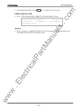
Press
the END key to return to the "Setting" screen.
Note:
To release the latch state, refer to Section 4.2.1.
Assigning signals
•
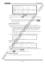
Press 2 on the "Setting" screen to display the "Input to logic gate" screen.
/ 4
I n p u t t o
l o g i c
g a t e
1 / 4
I n
# 1 (
0 -
0 7 1 ) :
2 1
I n
# 2 (
0 -
0 7 1 ) :
4
I n
# 3 (
0 -
0 7 1 ) :
6 7
I n
# 4 (
0 -
0 7 1 ) :
0
3
3
3
3
•
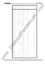
Assign signals to gates (In #1- #4) by entering the number corresponding to each signal
referring to Appendix B.
Note:
If signals are not assigned to all the gates #1-#4, enter 0 to the unassigned gate(s).
Repeat this process for other LEDs to be configured.
4.2.7 Testing
The sub-menu "Test" provides such functions as setting of test switches, manual starting of
automatic tests, forced operation of binary outputs, time measurement of the variable setting timer
and logic signal observation.
4.2.7.1 Setting the Switches
The automatic monitor function (A.M.F.) can be disabled by setting the switch [A.M.F] to "Off."
Disabling the A.M.F. inhibits trip blocking even in the event of a failure in the items being
monitored by this function. It also prevents failures from being displayed on the "ALARM" LED
and LCD described in Section 4.2.1. No events related to the A.M.F. are recorded, either.
Disabling A.M.F. is useful for blocking the output of unnecessary alarms during testing.
Note:
Set the switch [A.M.F] to "Off" before applying the test inputs, when the A.M.F is disabled.
When a three-phase voltage source is not available, the distance measuring element operation can
be tested using a single-phase voltage source by setting the switch [Z1S-1PH] to "On". This is not
fit for the high-accuracy test, though.
The switch [ZB-CTRL] is used to test the Z1 characteristic with offset or not. When the switch
[ZB-CTRL] is set to "1", the Z1 is an offset characteristic. When the switch [ZB-CTRL] is set to
"2", the Z1 is a characteristic without offset.
Offset
characteristic
(setting "1")
X
R
X
(b) Quadrilateral
(a) Mho
Figure 4.2.7.1 Z1 Characteristics by [ZB-CTRL] Setting
www
. ElectricalPartManuals
. com
Summary of Contents for GRZ100-211B
Page 323: ... 322 6 F 2 S 0 8 3 4 w w w E l e c t r i c a l P a r t M a n u a l s c o m ...
Page 343: ... 342 6 F 2 S 0 8 3 4 w w w E l e c t r i c a l P a r t M a n u a l s c o m ...
Page 383: ... 382 6 F 2 S 0 8 3 4 w w w E l e c t r i c a l P a r t M a n u a l s c o m ...
Page 395: ... 394 6 F 2 S 0 8 3 4 w w w E l e c t r i c a l P a r t M a n u a l s c o m ...
Page 411: ... 410 6 F 2 S 0 8 3 4 w w w E l e c t r i c a l P a r t M a n u a l s c o m ...
Page 423: ... 422 6 F 2 S 0 8 3 4 w w w E l e c t r i c a l P a r t M a n u a l s c o m ...
Page 443: ... 442 6 F 2 S 0 8 3 4 w w w E l e c t r i c a l P a r t M a n u a l s c o m ...
Page 451: ... 450 6 F 2 S 0 8 3 4 w w w E l e c t r i c a l P a r t M a n u a l s c o m ...
Page 459: ... 458 6 F 2 S 0 8 3 4 w w w E l e c t r i c a l P a r t M a n u a l s c o m ...
Page 463: ...w w w E l e c t r i c a l P a r t M a n u a l s c o m ...


