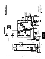
Right and Left Turn
Right
The gear pump (P2) is directly coupled to the hydrostat
through gear pump (P1). It supplies hydraulic pressure
to the steering control valve for turning the rear wheel
and maintaining 100 to 150 PSI (6.9 to 10.0 Bar) to the
low pressure side of the traction circuit. The pump takes
its suction from the hydraulic reservoir.
With the steering wheel in the neutral position (rear
wheel positioned straight ahead) and the engine run-
ning, the spool valve is in the center position. Flow en-
ters the steering control valve at Port (P) and goes
through the spool valve by–passing the steering cylin-
der. Flow leaves the control valve out port (PB) and con-
tinues through solenoid valve (S2) to the hydrostat.
When a right turn is made with the engine running, the
turning of the steering wheel positions the spool valve so
that flow goes through the top of the spool. Flow entering
the steering control valve at Port (P) goes through the
spool and is routed to two places. First, most of the flow
through the valve is by–passed out port (PB) back
through solenoid valve (S2) to the hydrostat. Second,
the remainder of the flow is drawn through rotary meter
(V1) and out port (R). Pressure moves the piston in the
direction for a right turn. The rotary meter ensures that
the oil flow to the cylinder is proportional to the amount
of the turning on the steering wheel. Fluid leaving the
cylinder flows back through the spool valve then out port
(T) and to the hydrostat.
The steering wheel and steering control valve return to
the neutral position when turning is complete.
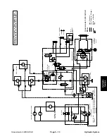
Left
When a left turn is made with the engine running, the
turning of the steering wheel positions the spool valve so
that flow goes through the bottom of the spool. Flow en-
tering the steering control valve at Port (P) goes through
the spool and is routed to two places. First, most of the
flow through the valve is by–passed out port (PB) back
through solenoid valve (S2) to the hydrostat. Second,
the remainder of the flow is drawn through rotary meter
(V1) and out port (L). Pressure moves the piston in the
direction for a left turn. The rotary meter ensures that the
oil flow to the cylinder is proportional to the amount of the
turning on the steering wheel. Fluid leaving the cylinder
flows back through the spool valve then out port (T) and
to the hydrostat.
The steering wheel and steering control valve return to
the neutral position when turning is complete.
Hydraulic System
Page 5 – 14
Greensmaster 3200/3200–D
Summary of Contents for 3200
Page 2: ...Greensmaster 3200 3200 D ...
Page 4: ...Greensmaster 3200 3200 D ...
Page 6: ...Greensmaster 3200 3200 D ...
Page 12: ...Safety Page 1 6 Greensmaster 3200 3200 D ...
Page 14: ...Equivalents and Conversions Product Records and Maintenance Page 2 2 Greensmaster 3200 3200 D ...
Page 17: ...Product Records and Maintenance Page 2 6 Greensmaster 3200 3200 D ...
Page 72: ...Perkins Diesel Engine Page 4 30 Greensmaster 3200 D ...
Page 113: ...Hydraulic System Greensmaster 3200 3200 D Page 5 41 Hydraulic System ...
Page 161: ...Hydraulic System Greensmaster 3200 3200 D Page 5 89 Hydraulic System ...
Page 173: ...Hydraulic System Greensmaster 3200 3200 D Page 5 101 Hydraulic System ...
Page 234: ...Wheels and Brakes Page 7 12 Greensmaster 3200 3200 D ...
Page 261: ...Cutting Units Greensmaster 3200 3200 D Page 8 27 Cutting Units ...
Page 273: ......
Page 274: ...Commercial Products FORM 96 900 SL E The Toro Company 1997 Printed in U S A ...


