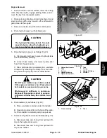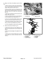
12. Install muffler as follows (Fig. 34):
A. Secure muffler to the pump plate with two cap
screws.
B. Install muffler shield to the muffler and pump
plate with four cap screws.
C. Secure exhaust plate to the engine exhaust
manifold with four cap screws and flat washers.
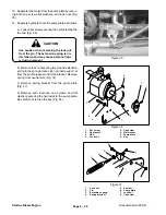
13. Install air cleaner as follows (Fig. 33):
A. Secure air cleaner and bracket to the pump
plate.
B. Connect hose leading to the radiator to the
cleaner.
C. Route and connect hose, leading from the clean-
er to the engine valve cover, to the valve cover and
cleaner.
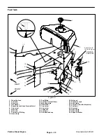
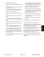
14. Install fuel tank and hydraulic reservoir as follows:
A. Position mounting plate and tanks onto the
frame.
B. If the oil cooler is not installed, Connect hydrau-
lic hose to the hydraulic oil filter (Fig. 32).
C. Connect hydraulic hose to the welded fitting on
the tube leading into rear bulkhead (Fig. 31).
D. Remove plug from the pump inlet hose and gear
pump. Install pump inlet hose to the gear pump with
hose clamp (Fig 29).
E. Connect expansion tank hose (25) to the radia-
tor elbow (26) (Fig. 26).
F. Connect fuel hose (36) and expansion tank hose
(50) to the support bracket (14). Connect fuel hose
(35) to the number three fuel injector (Fig. 28).
G. Make sure hoses are secured to the frame and
supports with cable ties and hose clamps.
H. Connect fuel hose (36) to fuel filter (49) (Fig. 28).
I. Secure tank mounting plate (13) to the support
bracket (28) and frame with three cap screws (6)
and two flat washers (14) (Fig. 27).
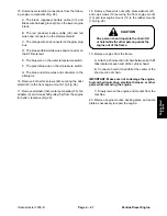
15. Connect hydraulic oil cooler if installed (Fig. 30).
A. Connect tube and O–ring to hydraulic fitting on
the hydraulic reservoir.
B. Connect tube and O–ring to hydraulic fitting on
the oil filter.
16. Install screen (10) into the radiator support (8) (Fig.
26).
17. Install console shroud to the control panel.
18. Make sure both fuel shutoff valves are open (see
Fuel Shutoff Valves). Fill fuel tank with fuel (see Fill Fuel
Tank). Check tank and hoses for leaks.
19. Fill cooling system with coolant (see Check Cooling
System). Check radiator and hoses for leaks.
20. Fill hydraulic reservoir with hydraulic oil (see Check
Hydraulic System Fluid in Chapter 5 – Hydraulic Sys-
tem). Check reservoir and hoses for leaks.
21. Bleed fuel system (see Bleeding Fuel System).
22. Adjust throttle control lever and cable (see Throttle
Adjustment).
Perkins Diesel
Engine
Greensmaster 3200–D
Page 4 – 29
Perkins Diesel Engine
Summary of Contents for 3200
Page 2: ...Greensmaster 3200 3200 D ...
Page 4: ...Greensmaster 3200 3200 D ...
Page 6: ...Greensmaster 3200 3200 D ...
Page 12: ...Safety Page 1 6 Greensmaster 3200 3200 D ...
Page 14: ...Equivalents and Conversions Product Records and Maintenance Page 2 2 Greensmaster 3200 3200 D ...
Page 17: ...Product Records and Maintenance Page 2 6 Greensmaster 3200 3200 D ...
Page 72: ...Perkins Diesel Engine Page 4 30 Greensmaster 3200 D ...
Page 113: ...Hydraulic System Greensmaster 3200 3200 D Page 5 41 Hydraulic System ...
Page 161: ...Hydraulic System Greensmaster 3200 3200 D Page 5 89 Hydraulic System ...
Page 173: ...Hydraulic System Greensmaster 3200 3200 D Page 5 101 Hydraulic System ...
Page 234: ...Wheels and Brakes Page 7 12 Greensmaster 3200 3200 D ...
Page 261: ...Cutting Units Greensmaster 3200 3200 D Page 8 27 Cutting Units ...
Page 273: ......
Page 274: ...Commercial Products FORM 96 900 SL E The Toro Company 1997 Printed in U S A ...


