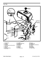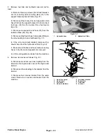
Low–Speed Adjustment (Fig. 13 and 14)
1. Make sure machine is parked on a level surface with
the parking brake engaged and the cutting units low-
ered. Allow engine to run for at least ten minutes to bring
it to operating temperature.
2. Position throttle control lever to the low idle position
(against the stop plate).
3. Lift up seat to access the engine.
4. Loosen cap screw and lock nut securing the throttle
cable clamp to the throttle control cable and front engine
mount.
5. Loosen lock nut on the low–speed set bolt.
6. Adjust engine speed between 1450 and 1550 RPM
by rotating the low–speed set bolt. Make sure throttle
control lever is against the stop plate. Tighten lock nut.
7.
Tighten cap screw and lock nut securing the throttle
cable clamp to the throttle control cable and front engine
mount.
Perkins Diesel Engine
Page 4 – 10
Greensmaster 3200–D
Summary of Contents for 3200
Page 2: ...Greensmaster 3200 3200 D ...
Page 4: ...Greensmaster 3200 3200 D ...
Page 6: ...Greensmaster 3200 3200 D ...
Page 12: ...Safety Page 1 6 Greensmaster 3200 3200 D ...
Page 14: ...Equivalents and Conversions Product Records and Maintenance Page 2 2 Greensmaster 3200 3200 D ...
Page 17: ...Product Records and Maintenance Page 2 6 Greensmaster 3200 3200 D ...
Page 72: ...Perkins Diesel Engine Page 4 30 Greensmaster 3200 D ...
Page 113: ...Hydraulic System Greensmaster 3200 3200 D Page 5 41 Hydraulic System ...
Page 161: ...Hydraulic System Greensmaster 3200 3200 D Page 5 89 Hydraulic System ...
Page 173: ...Hydraulic System Greensmaster 3200 3200 D Page 5 101 Hydraulic System ...
Page 234: ...Wheels and Brakes Page 7 12 Greensmaster 3200 3200 D ...
Page 261: ...Cutting Units Greensmaster 3200 3200 D Page 8 27 Cutting Units ...
Page 273: ......
Page 274: ...Commercial Products FORM 96 900 SL E The Toro Company 1997 Printed in U S A ...


