Removing Hydraulic Reservoir (Fig. 85)
1. Before removing any parts from the hydraulic sys-
tem, park machine on a level surface, set brake, lower
cutting units, and stop engine.
CAUTION
Operate all hydraulic controls to relieve sys-
tem pressure and avoid injury from pressur-
ized hydraulic oil. Controls must be oper-
ated with the ignition switch in RUN and the
when pressure has been relieved. Remove
key from the ignition switch.
engine OFF. Return ignition switch to OFF
2. Clean oil filter assembly (8) and hose connection,
hydraulic tank (6) and hose connections, and pump inlet
hose connections at the hydrostat.
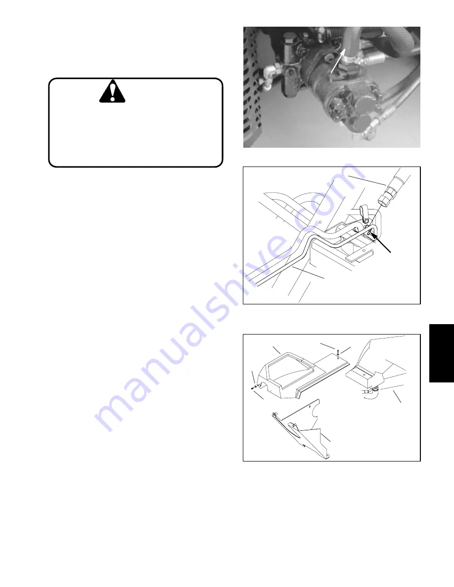
3. Place a suitable container under the hydrostat to
collect hydraulic oil. Clamp pump inlet hose to prevent
drainage. Remove pump inlet hose from hydrostat and
direct to container. Release clamp from hose (Fig. 86).
4. Disconnect hose assembly from the hydraulic fitting
welded to the reel motor case drain tube located below
the right side of the frame. Allow hose to drain to a suit-
able container (Fig. 87).
5. Disconnect formed hose (21) from hydraulic barb fit-
ting (9). Allow hose to drain to a suitable container.
6. Remove cap screw and flat washer securing the
console shroud to the hydraulic tank. Remove both cap
screws and flat washers securing the console shroud to
the lower panel (Fig. 88).
7. Remove three hex head screws and flat washers
securing the mounting plate (11) to the frame. Two
screws are located on the top of the plate at the front cor-
ners of the fuel tank. The third screw is in front of the cas-
tor fork and below the plate.
8. Tilt mounting plate (11) up by lifting at the rear of the
machine. Prop up plate securely. Remove four cap
screws (16) and flat washers (12) securing the hydraulic
tank (6) to the mounting plate.
9. Remove hydraulic tank (6) from the mounting plate
(11).
10. Hoses (31 and 32), hydraulic fittings (9,1, and 2),
and O–rings (29, 27, and 25) may be removed from the
hydraulic tank (6).
PUMP INLET HOSE
Figure 86
1
2
WELDED
FITTING
Figure 87
1. Hose
assembly
2. Case
drain
tube
2
3
3
1
4
5
6
Figure 88
1. Cap
screw
4. Console
shroud
2. Cap
screw
5. Hydraulic
tank
3. Flat
washer
6. Lower
panel
Hydraulic
System
Greensmaster 3200/3200–D
Page 5 – 99
Hydraulic System
Summary of Contents for 3200
Page 2: ...Greensmaster 3200 3200 D ...
Page 4: ...Greensmaster 3200 3200 D ...
Page 6: ...Greensmaster 3200 3200 D ...
Page 12: ...Safety Page 1 6 Greensmaster 3200 3200 D ...
Page 14: ...Equivalents and Conversions Product Records and Maintenance Page 2 2 Greensmaster 3200 3200 D ...
Page 17: ...Product Records and Maintenance Page 2 6 Greensmaster 3200 3200 D ...
Page 72: ...Perkins Diesel Engine Page 4 30 Greensmaster 3200 D ...
Page 113: ...Hydraulic System Greensmaster 3200 3200 D Page 5 41 Hydraulic System ...
Page 161: ...Hydraulic System Greensmaster 3200 3200 D Page 5 89 Hydraulic System ...
Page 173: ...Hydraulic System Greensmaster 3200 3200 D Page 5 101 Hydraulic System ...
Page 234: ...Wheels and Brakes Page 7 12 Greensmaster 3200 3200 D ...
Page 261: ...Cutting Units Greensmaster 3200 3200 D Page 8 27 Cutting Units ...
Page 273: ......
Page 274: ...Commercial Products FORM 96 900 SL E The Toro Company 1997 Printed in U S A ...


