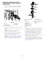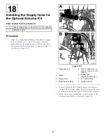
Figure 118
Agitation Valve Manifold
1.
Stem retainer
7.
Back seating O-ring (0.676
inch / 0.07 inch)
2.
Valve stem
8.
Valve-seat ring
3.
Stem port
9.
Manifold body
4.
Stem retainer
10.
Ball valve
5.
End-cap fitting
11.
Quick connect
6.
End-cap-seal O-ring
(0.796 inch / 0.139 inch)
Figure 119
Section Valve Manifold
1.
Valve-stem seat
7.
End cap O-ring (0.796 inch
/ 0.139 inch)
2.
Valve-stem assembly
8.
Back seating O-ring (0.676
inch / 0.07 inch)
3.
Stem port
9.
Ball seat
4.
Stem retainer
10.
Manifold body
5.
Outlet fitting O-ring (0.737
inch / 0.103 inch)
11.
Ball valve
6.
End-cap fitting
12.
End-cap-fitting assembly
3.
Turn the valve stem so that the ball is in the O
PEN
position (
).
Note:
The valve stem should be parallel with the valve
flow and the ball should slide out.
4.
Remove the stem retainer from the slots in the stem
port in the manifold (
and
5.
Remove the stem retainer and valve-stem seat from the
manifold (
and
).
6.
Reach into the manifold body and remove the
valve-stem assembly (
and
).
7.
Clean the inside of the manifold and exterior of the
ball valve, valve-stem assembly, stem capture, and end
fittings.
56
Summary of Contents for 136-0372
Page 61: ...Schematics Flow Diagram Rev A 61...
Page 62: ...Notes...
Page 63: ...Notes...
Page 64: ......


