Wiring Table—Right Spray Valve
Wire color codes—DIN wire
harness
Wire color codes—3-pin
adapter
Brown
Pink
Blue
Black
Yellow/green
White
2.
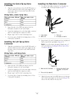
Insert the wire of the DIN wire harness into the
butt-splice connector of the 3-pin adapter (
Figure 34
1.
3-pin adapter
3.
Butt-splice connector
2.
DIN wire harness
4.
Exposed wire 9.5 mm (3/8
inch)
3.
Center the crimping tool over the butt-splice connector
and wires and crimp the connector securely (
).
Figure 35
1.
3-pin adapter
3.
Connector (center spray)
2.
Wire harness branch (left
spray)
4.
Connector (right spray)
4.
Repeat steps
and
for the 2 remaining wires.
5.
Use a heat gun to shrink the insulating sleeves of the 3
butt-splice connectors (
).
Figure 36
18
Summary of Contents for 136-0372
Page 61: ...Schematics Flow Diagram Rev A 61...
Page 62: ...Notes...
Page 63: ...Notes...
Page 64: ......


