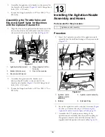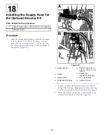
Figure 77
1.
Quick-connect fitting
(bypass manifold)
5.
Retainer (large)
2.
90° quick-connect fitting
6.
90° barbed fitting
3.
Section bypass hose—2.5
x 146 cm (1 x 57-1/2
inches)
7.
Bulkhead fitting (sprayer
tank)
4.
Retainer (small)
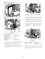
2.
Route the section bypass hose around the right frame
channel toward the bulkhead fitting in the sprayer tank
as shown in
Figure 78
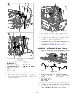
1.
Section bypass hose—2.5 x 146 cm (1 x 57-1/2 inches)
3.
Assemble the 90° barbed fitting of the section bypass
hose into the bulkhead fitting (
).
4.
Secure the 90° fitting to the bulkhead fitting (
with the retainer (large) that you removed in step
of
Removing the Section Bypass Hose (page 16)
.
Installing the Section Supply Hoses
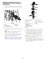
1.
Route the left, center, and right boom-supply hoses to
the boom-section valves as shown in
.
Figure 79
1.
Left boom-supply hose—2
x 213 cm (3/4 x 83-7/8
inches)
3.
Right boom-supply
hose—2 x 142 cm (3/4 x
55-7/8 inches)
2.
Center boom-supply
hose—2 x 67 cm (3/4 x
26-5/16 inches)
2.
Assemble the straight barbed fitting of the supply hose
for the left boom-supply hose onto the quick-connect
fitting at the left-boom-section valve (
).
38
Summary of Contents for 136-0372
Page 61: ...Schematics Flow Diagram Rev A 61...
Page 62: ...Notes...
Page 63: ...Notes...
Page 64: ......


