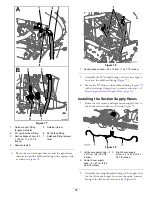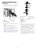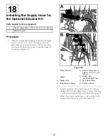
Figure 107
1.
Boom-section-bypass adjustment knobs
12.
Turn on the left boom and turn off the right boom.
13.
Adjust the right boom-bypass knob (
) until
the pressure reading is at the previously adjusted level
(typically 2.75 bar or 40 psi).
14.
Turn on the right boom and turn off the center boom.
15.
Adjust the center boom-bypass knob (
) until
the pressure reading is at the previously adjusted level
(typically 2.75 bar or 40 psi).
16.
Turn all the booms off.
17.
Turn the pump off.
Note:
Calibration is now complete.
Positioning the
Agitation-Bypass-Valve Knob
•
The agitation bypass valve is in the full O
PEN
position as
shown in
•
The agitation bypass valve is in the C
LOSE
(0) position as
shown in
•
The agitation bypass valve is in an I
NTERMEDIATE
(adjusted relative to the pressure gauge for the sprayer
system) position as shown in
Figure 108
1.
Open
3.
Intermediate position
2.
Closed (0)
Calibrating the
Agitation-Bypass Valve
Service Interval:
Yearly
Select an open flat area to perform this procedure.
1.
Fill the spray tank with clean water.
2.
Verify the agitation-control valve is open. If it has been
adjusted, open it completely at this time.
3.
Set the parking brake and start the engine.
4.
Set the range selector to N
EUTRAL
.
5.
Set the pump switch to the O
N
position.
6.
Press the accelerator pedal to achieve maximum engine
speed and set the throttle lock.
7.
Set the 3 boom-section valves to the O
FF
position.
8.
Set the master-boom switch to the O
N
position.
9.
Set the system pressure to M
AXIMUM
.
10.
Press the agitation switch to the O
FF
position and read
the pressure gauge.
•
If the reading remains at 6.9 bar (100 psi) the
agitation-bypass valve is properly calibrated.
•
If the pressure gauge reads differently continue to
the next step.
11.
Adjust the agitation-bypass valve (
) on
the backside of the agitation valve until the pressure
reading on the gauge is 6.9 bar (100 psi).
Figure 109
1.
Agitation-bypass valve
2.
Master-boom bypass
12.
Press the pump switch to the O
FF
position, shift the
throttle lever to the I
DLE
position, and turn the ignition
switch to the O
FF
position.
51
Summary of Contents for 136-0372
Page 61: ...Schematics Flow Diagram Rev A 61...
Page 62: ...Notes...
Page 63: ...Notes...
Page 64: ......


