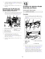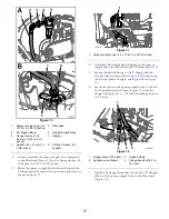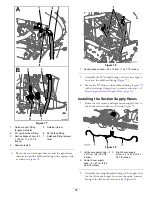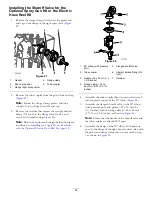
Figure 69
1.
Bypass hose—2.5 x 110 cm (1 x 43-1/2 inches)
4.
Align the flange of the straight barbed fitting and
gasket—25 x 35 mm (1 x 1-3/8 inches) with the flange
of the bypass valve (
5.
Secure the straight barbed fitting to the bypass valve
(
) with a flange clamp—40 to 64 mm (1-9/16
to 2-1/2 inches).
15
Installing the Sprayer Supply
Hose
Parts needed for this procedure:
1
Sprayer supply hose—2.5 x 73 cm (1 x 28-7/8
inches)—machines without the optional eductor kit
2
Flange clamp—40 to 64 mm (1-9/16 to 2-1/2 inches)
2
Gasket—25 x 35 mm (1 x 1-3/8 inches)
1
Support clamp—machines without the optional
eductor kit
1
Flange-head bolt (5/16 x 3/4 inch)—machines without
the optional eductor kit
1
Flange locknut (5/16 inch)—machines without the
optional eductor kit
1
Lower supply hose—25 x 66 cm (1 x 25-3/4 inches)
machines with the optional eductor kit
1
Retainer (small)—machines with the optional eductor
kit
1
Upper supply hose—25 x 22 cm (1 x 8-5/8 inches)
machines with the optional eductor kit
Installing the Sprayer Supply
Hose—Machine without the Optional
Eductor Kit
If your machine has the optional eductor kit, skip to
the Lower Sprayer Supply Hose—Machines with the Optional
Eductor Kit (page 36)
.
1.
Align the 90° flanged elbow of the sprayer supply
hose—2.5 x 73 cm (1 x 28-7/8 inches) with a
gasket—25 x 35 mm (1 x 1-3/8 inches) to the flange of
the filter head (
34
Summary of Contents for 136-0372
Page 61: ...Schematics Flow Diagram Rev A 61...
Page 62: ...Notes...
Page 63: ...Notes...
Page 64: ......


