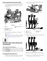
Removing the Section Bypass Hose
1.
Remove the retainer that secures the 90° barbed fitting
of the section bypass hose for the boom-section valves
from the bulkhead fitting at the back of the sprayer
tank (
Figure 28
1.
Retainer
3.
Bulkhead fitting (sprayer
tank)
2.
90° barbed fitting—section
bypass hose
(boom-section valves)
2.
Remove the 90° barbed fitting from the bulkhead
fitting (
Note:
Retain the retainers for installation in
the Section Bypass Hose (page 37)
; you no longer need
the bypass hose for the boom-section valves.
8
Replacing the Valve Electrical
Connectors
Parts needed for this procedure:
6
Cable ties
5
3-pin adapter
1
4-pin adapter
Preparing the Wire Harness
1.
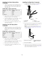
At the back of the machine, remove the 3 tie wraps that
secure the convoluted tubing and inline-fuse block to
the wire harness for the branch labeled
RIGHT SPRAY
VALVE
as shown in
Figure 29
1.
DIN connectors
4.
Inline-fuse block
2.
Label
5.
Cable ties
3.
Convoluted tubing
2.
Remove 76 mm (3 inches) section of convoluted tubing
as shown in
Figure 30
1.
Removed section of convoluted tube—76 mm (3 inches)
3.
Position the convoluted tubing toward the main branch
of the wire harness as shown in
16
Summary of Contents for 136-0372
Page 61: ...Schematics Flow Diagram Rev A 61...
Page 62: ...Notes...
Page 63: ...Notes...
Page 64: ......


