Installing the Flow Meter
1.
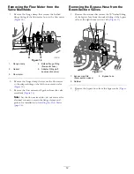
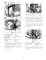
Align the flow meter to the reducer adapter at the left
spray valve with the arrow of the flow meter pointing
right (
Figure 53
1.
Arrow
4.
Gasket
2.
Flow meter
5.
Reducer adapter (left
spray valve)
3.
Flange clamp
2.
Assemble the flow meter to the reducer adapter with
the gasket and flange clamp (
) that you
removed in step
and
of
from the Valve Manifolds (page 12)
.
3.
Assemble quick-connect fitting of the flow-meter hose
with the quick-connect fitting at the master-spray valve
(
).
Figure 54
1.
Quick-connect fitting
(master-spray valve)
3.
Retainer
2.
Quick-connect fitting
(flow-meter hose)
4.
Flow-meter hose
4.
Secure the hose fitting to the valve fitting with the
retainer (
) that is provided with the flow-meter
hose.
5.
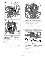
Align the barbed flange fitting of the flow-meter hose
and the gasket that you removed in step
of
the Flow Meter from the Valve Manifolds (page 12)
with the flange at the inlet of the flow meter (
).
Figure 55
1.
Flange (flow meter)
3.
Gasket
2.
Barbed flange fitting
4.
Flange clamp
6.
Secure the flow-meter hose to the flow meter with
a clamp (
) that you removed in step
of
Removing the Flow Meter from the Valve Manifolds
(page 12)
26
Summary of Contents for 136-0372
Page 61: ...Schematics Flow Diagram Rev A 61...
Page 62: ...Notes...
Page 63: ...Notes...
Page 64: ......

