Removing the Flow Meter from the
Valve Manifolds
1.
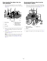
Remove the flange clamp that secures the barbed
flange fitting of the flow meter hose to the flow meter
(
).
Figure 16
1.
Flange clamp
4.
Barbed flange fitting
(flow-meter hose)
2.
Gasket
5.
Adapter fitting (left
boom-section valve)
3.
Flow meter
2.
Remove the flange clamp that secure the flow meter
to the adapter fitting at the left boom-section valve
(
).
3.
Remove the flow meter and 2 gaskets from the valve
manifolds (
Note:
Set the flow meter aside—do not remove the
electrical connector; retain the flange clamps and
gaskets for installation in
(page 26)
.
Removing the Bypass Hose from the
Boom-Section Valves
1.
Remove the retainer that secures the 90° barbed fitting
of the bypass hose from the socket fitting of the bypass
valve at the right boom section valve (
Figure 17
1.
Bypass manifold
(boom-section valves)
3.
Bypass hose
2.
Retainer
2.
Remove the bypass hose from the bypass valve (
12
Summary of Contents for 136-0372
Page 61: ...Schematics Flow Diagram Rev A 61...
Page 62: ...Notes...
Page 63: ...Notes...
Page 64: ......


