background image

INSTRUCTION MANUAL

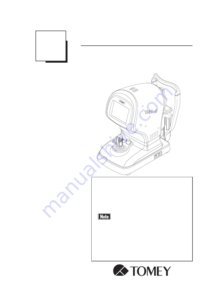
Topographic Modeling System

TMS-5

Read this manual thoroughly before using the 

instrument to ensure correct and safe operation.

Contact Tomey Corporation or our local distributor 

if you have any questions or you encounter any 

problems during operation.


■ Always follow the operation 

procedures described in this manual.


■ Keep this manual in a readily accessible 

location while operating this instrument.


■ Contact our local distributor if you lose 

this manual.

229A9090-1D

Summary of Contents for TMS-5

Page 1: ...tion Contact Tomey Corporation or our local distributor if you have any questions or you encounter any problems during operation Always follow the operation procedures described in this manual Keep th...

Page 2: ......

Page 3: ...he personal computer and Isolation transformer Contact our local distributor or Tomey Corporation if you have any questions Use a personal computer conforming to IEC60950 1 and an Isolation transforme...

Page 4: ...1 or equivalent safety requirements or that conform to IEC60950 and whose power source is insulated with the attached Isolation transformer in order to satisfy the safety requirements regarding the m...

Page 5: ...damage the caution labels on the instrument The caution labels are provided at two locations as shown below If a label is damaged or becomes illegible please contact Tomey Corporation or our local dis...

Page 6: ...i 4 This page is intentionally blank...

Page 7: ...CEDURES Describes information required for installing and using the instrument 4 TECHNICAL INFORMATION Describes useful technical information about the instrument 5 INSPECTION AND MAINTENANCE Describe...

Page 8: ...ecaution that if unheeded could result in a hazardous situation where there is a possibility of serious injury or death This is a precaution that if unheeded may result in a situation where there is a...

Page 9: ...the instrument patient s side 2 5 2 4 Screen of the main unit 2 6 2 4 1 Ring topo mode screen 2 6 2 4 2 Slit mode screen 2 8 2 5 Personal computer screen 2 10 2 5 1 Examination List screen 2 10 2 5 2...

Page 10: ...3 26 3 6 2 Analysis type 3 46 3 6 3 Map scale 3 68 3 6 4 Quantitative index 3 76 3 6 5 Optional function of map 3 80 3 6 6 Other map display modes and applications 3 91 3 7 Output of results 3 97 3 7...

Page 11: ...fe 5 2 5 3 Inspection 5 2 5 3 1 Calibration verification ring topo mode 5 3 5 3 2 Calibration verification slit mode 5 4 5 4 Routine maintenance 5 5 5 4 1 Forehead pad and chin rest 5 5 5 4 2 Exterior...

Page 12: ...iii 4 8 3 Operating environment 8 3 8 4 Classification 8 3 8 5 Declaration of conformity to EMC 8 4 8 6 Classification by ISO15004 2 Group 2 instrument 8 8 9 INDEX 9 1...

Page 13: ...cals or vapor may enter the instrument and result in fire Check the frequency voltage and allowable current or power consumption of the power source Otherwise fire or electric shock may occur Connect...

Page 14: ...t be conducted correctly The instrument also may topple over or fall down resulting in fire or a serious accident Install the instrument between the patient and physician so that they can face each ot...

Page 15: ...ckness directly to correct the eye refractive power Other examination methods should also be used in conjunction with the above If the radius of corneal curvature of this instrument is used directly t...

Page 16: ...lting in mechanical failure or injuries Peel off the top sheet of chin paper and clean the forehead pad with a clean cloth before capturing an image of the next patient Clean the forehead pad and chin...

Page 17: ...e instrument Doing so may cause electric shock or failure of the instrument There is a high voltage section in the instrument Touching this section will result in death or serious injuries Disconnect...

Page 18: ...ove the packing materials Be careful not to lift the main unit up by directly holding the head chin rest forehead pad or joystick The instrument may be damaged Main unit Topographic Modeling System 1...

Page 19: ...idian value and minor meridian value is less than 0 2D Kf Direction and value of the meridian that intersects Ks at right angles are displayed f of Kf stands for flat MinK Direction and value of the m...

Page 20: ...analysis screens in each viewer MERGED TOPO Viewer Displays the analysis screen that uses MERGED TOPO data such as the MERGED TOPO map RING TOPO Viewer Displays the analysis screen that uses RING TOP...

Page 21: ...blue while above the normal range the color changes from a reddish color to bright colors Normalized scale Automatically assigns refractive powers according to the analysis result of the patient s ey...

Page 22: ...LCD with only the power lamp flashing when the instrument is not operated for the specified time Auto Power Off mode Touch any button to return to Normal mode Touch panel Allows you to change various...

Page 23: ...ystem that is designed to capture Scheimpflug images and topographer measurements of the anterior segment of the eye to provide information including anterior posterior corneal topography anterior pos...

Page 24: ...1 12 This page is intentionally blank...

Page 25: ...sonal computer that receives the data from the main unit and displays saves and manages the data In addition the captured data is analyzed in a variety of ways 3 Isolation transformer Optional A plug...

Page 26: ...2 2 2 1 2 Connection diagram Optional Optional AC power input AC power input USB cable Non ME device ME device Isolation transformer Personal computer Main unit...

Page 27: ...splays the capture screen and various setting screens Touch the touch panel buttons shown on the LCD to make various settings and operate the instrument 3 Joystick Tilting the joystick to the left rig...

Page 28: ...utton Switches whether to start capturing in automatic mode or manual mode 10 MODE button Switches the capture mode 11 PACKING button Pressing this button for 3 seconds moves the head to the lowest po...

Page 29: ...atient s eye are captured in ring mode through this capture window 2 Slit cone capture window Images of a patient s eye are captured in slit mode through this capture window 3 Chin rest The patient pl...

Page 30: ...tiated by colors 2 Timer for capturing Displays available time left for capturing images Counts down from 60 seconds 3 Mode display Displays the current capture mode 4 Auxiliary function display Displ...

Page 31: ...s eye with this position 11 Start Stop button Controls the main unit of TMS to start and stop capturing 12 Captured data display Displays the number of images captured on the personal computer with g...

Page 32: ...lays 3D scan and Enhanced 2D scan indicating normal capture or Calibration Verification indicating a calibration check Refer to 3 5 2 Temporary setting Temporary for how to switch this auxiliary funct...

Page 33: ...e center of the patient s eye with this position 9 Captured data display Displays the number of images to be captured Refer to 3 5 Various settings of main unit for how to change the number of images...

Page 34: ...icking an icon 3 Update button Set conditions to search for the patient A list of patients that match the set conditions is displayed Also register new patient or modify information for an existing pa...

Page 35: ...or the selected patient Select Examination Type from the menu to display the examination type list Modify Loads the patient data from the database to update the existing data Image Frame Displays a th...

Page 36: ...ion License Version b Tool bar 1 Details of examination data Displays the Examination Data screen Same as Details of Examination Data in the View menu 2 Update Loads the patient data from the database...

Page 37: ...nformation search Enter the patient ID and name to search for a patient Refer to 3 8 1 Handling patient ID 2 Patient list Lists the patient IDs found by the search The patient ID and name are displaye...

Page 38: ...Examination data tree Displays the examination data in tree format according to the examination date The tree for the specified date and examination data can be marked Select a date or examination dat...

Page 39: ...e 25 or 31 is shown according to the number of ring cones to be used 3 Connected device The S N serial number of the applicable TMS is shown If multiple devices are connected select the appropriate TM...

Page 40: ...splayed on the image display area Pressing a button displays the corresponding image in the top section of the display area Numbers are assigned to buttons from 1 in the order of smaller misalignment...

Page 41: ...d 3 Inspected eye The inspected eye is displayed OD OS 4 Ring topo image display A Mires ring image and Mires plot are displayed 5 Slit image display The image captured in slit mode is displayed Use t...

Page 42: ...mode and slit mode and the corresponding analysis results and displays the Map MERGED screen 9 Cancel button Cancels analysis and returns to the Capture screen 10 Manual button Allows you to set the c...

Page 43: ...chronological order from the upper left to the lower right The offset value is shown at the lower right of each image and the analyzed area AA which can be analyzed at the lower left Double click the...

Page 44: ...or capturing images is displayed 25 31 3 Inspected eye The inspected eye is displayed OD OS 4 PP picture perfect The picture perfect status when capturing an image is displayed 5 Patient s name The pa...

Page 45: ...2 21 8 Manual button Allows you to set the corneal center when it cannot be detected on the captured image 9 Cancel button Returns to the Pre Map screen or Capture screen without performing analysis...

Page 46: ...Preview Displays a print preview of all analysis screens of the current viewer Close Closes the Analysis screen and returns to the previous screen 2 View button Analysis screen Switches various analys...

Page 47: ...sults 8 Transmissivity setting button Sets the transmissivity of the map 5 levels of transmissivity between the range 0 and 100 are shown in increments of 25 9 Analysis screen switch tab Switches the...

Page 48: ...2 24 11 Patient information Inspection date and time Displays the patient information and the inspection date and time 12 Inspected eye The inspected eye is displayed OD Right OS Left...

Page 49: ...2 25 a MERGED TOPO viewer Thumbnail Image Single Map 4Maps 6Maps Fourier Map Merged Calculation Slit Calculation...

Page 50: ...2 26 Ectasia Screening IOL Screening b RING TOPO viewer Single Map Fourier Map Klyce Corneal Statistics Keratoconus Screening Ring Calculation...

Page 51: ...are detachable and the instrument may drop resulting in injuries Install the instrument in a location not subject to direct sunlight high temperature and humidity or air containing dust salt and or su...

Page 52: ...on the power cord or squash the power cord Fire or electric shock may occur Fully insert the power plug into the outlet Faulty contact allowing any metal to contact the exposed terminals of the plug o...

Page 53: ...ained with in a sealed component in the sealed head of the main unit There are no user servicable components in the head Never open the panel of the head for any reason Also if strong mechanical impac...

Page 54: ...the steps below to attach the hood 1 Insert holder L and holder R 1 into the chin rest Fig 1 Do not force the holders Otherwise components may be damaged 2 Insert the cover 2 into holder L R Pay atte...

Page 55: ...switch is set to the right 1 Connect the USB connector 2 of the main unit and that of the personal computer with the attached USB cable 2 Connect the power cord of the personal computer to the outlet...

Page 56: ...he measurement section does not move even though the joystick is operated while the measurement section stopper is locked When moving or storing the instrument align the top section with the bottom se...

Page 57: ...seconds or so and turn it on again 1 Turn on the power switches of the isolation transformer and personal computer to start Windows 2 Double click TOMEY Measurement 1 on the personal computer The log...

Page 58: ...ician Fig 7 The initialization process automatically starts when the main unit reaches the point farthest from the patient The ring topo mode screen Fig 8 appears when initialization is completed Beca...

Page 59: ...patient information Register a new patient Perform measurement without registering the patient Refer to 3 8 1 Handling of patient ID for details on how to recall the registered patient ID and registe...

Page 60: ...ting the patient s eye or nose Also be sure that the patient does not place their hands or fingers near any moving section of the instrument Doing so may cause injury 1 Use the joystick to move the he...

Page 61: ...d fingers The patient may be injured by the movement of the head or chin rest The chin rest paper is provided to keep the chin rest clean Use this paper for the chin rest as well as the patient to use...

Page 62: ...position and fine operation for finely adjusting the position of the head The joystick button is located on the top of the joystick a Forward backward right and left Hold the joystick and slide the b...

Page 63: ...ight left position of the center point so that it is near the center of the pupil Tilt the joystick toward the patient side until the laser center point 3 dim small light appears from the left of the...

Page 64: ...and numbers are assigned in the order of smaller offset misalignment The image with the smallest offset misalignment is displayed in the upper section of the image display area immediately after capt...

Page 65: ...pture images again for the number of deleted images When deleting all the captured images Right click the image to be deleted on the Capture screen Fig 4 to open the Map Options Menu Fig 6 Check the C...

Page 66: ...3 3 Selecting the capture mode 2 Use the joystick to position the patient s eye on the screen 3 Align the reflection 1 at the corneal center with the center of the center ring 2 4 Tilt the joystick ba...

Page 67: ...or the same patient click the Cancel button 6 on the Exam MERGED screen Fig 4 to return to the Capture screen Fig 5 Right click an image captured in slit mode to open the Map Options Menu Fig 6 Check...

Page 68: ...ptured 3 3 Touching the Exit button 4 displays the 2D scan screen Fig 3 for 2D capturing 4 Specify the angle for capturing images Touch a number displayed on the screen 5 to turn the angle indicator b...

Page 69: ...green on the image of the cornea Mires Misalignment of focusing in the X Y and Z axes is indicated in the offset display 2 Check that the center of the Mires the inner mostring with green dots is alig...

Page 70: ...ional images in series or to display the next or previous captured images one by one 3 Touch the Mire Slit OK button 6 to save images captured in ring topo mode and slit mode including the correspondi...

Page 71: ...e of the tabs 2 listed on the left of the screen to select the setting item and set conditions as needed on the corresponding screen Touch the Top tab 3 after setting is complete to return to the prev...

Page 72: ...s the mode when right and left is changed in slit mode ON Enables the mode change assist function OFF Disables the mode change assist function Default AA Default Alignment Assist Define the default se...

Page 73: ...3D mode 32 Captures 32 images 64 Captures 64 images d 2D scan Setup Define settings for capturing 2D images in slit mode on this screen 2D scan Images Set the number of images to be scanned in 2D mod...

Page 74: ...n of auxiliary functions Switch the setting between normal capture and the auxiliary function for calibration check Capture Normal capturing of images Calibration Calibration checks Verification Align...

Page 75: ...s of the anterior segment of the eye in 3D mode 2D scan Captures images of the anterior segment of the eye in 2D mode Calibration Calibration checks Verification Enhanced 2D scan Image level Set the n...

Page 76: ...1 Basic operation Click the Mires Slit OK button 1 on the Exam MERGED screen Fig 1 Or select the examination data 2 on the Examination List screen Fig 2 to display the Analysis screen Fig 3 1 Fig 1 2...

Page 77: ...eening IOL Screening Click the transmissivity setting button 5 to change the transmissivity of the map 5 levels of transmissivity between the range 0 and 100 are shown in increments of 25 Click the vi...

Page 78: ...the pupil are shown 3 Pupil offset Offset of the pupil center is shown 4 PP picture perfect AS Auto Shot Whether or not the image was captured with the picture perfect function and Auto Shot function...

Page 79: ...map for details 7 Map scale The scale type currently applied is shown Click the description to display the menu that allows you to change the scale Selectable scales vary depending on map types Refer...

Page 80: ...ian Distance from center of analysis area mm Click the mark in the center of the map to delete the measured distance displayed Distance between two points When measuring the distance between two optio...

Page 81: ...same basic functions of the Single Map are available Click a map type 1 to change the map type c 6Maps 6 types of maps can be displayed simultaneously on the multi type map screen The same basic funct...

Page 82: ...are listed In addition an analyzed map and CCD image are also displayed as thumbnails Double clicking a thumbnail automatically jumps to d Image screen and enlarges the selected thumbnail Click a map...

Page 83: ...s Click a map type 1 to change the map type f Merged Calculation Ring Calculation The following information appears Mean ring power The average refractive power of each ring on the map is displayed in...

Page 84: ...hat the value was calculated manually Drag Point 1 4 and or Point 2 5 to correct it manually Click the left right arrow buttons 6 7 for each Point to in fine increments move the Point Click the AUTO b...

Page 85: ...ll down menu Changing slit image Click the change slit image button 2 to select the slit image to be displayed The slit image can also be changed by dragging line 3 on the CCD image Click the automati...

Page 86: ...he slit image 8 The unit is millimeters Epi stands for Epithelium and Endo for Endothelium Vaulting The distance between 2 points specified as Vaulting 1 and Vaulting 2 appears on the top of the slit...

Page 87: ...1 checked to move the corresponding point in fine increments Click the CLEAR button 13 to delete all data displayed on the image Click the Save button 22 to save the information displayed on the image...

Page 88: ...een appears Fig 4 when either Setting button is clicked Click the OK button to register the current setting as a custom value and the Setting button name turns blue After this the current setting can...

Page 89: ...toconus and Pellucid marginal corneal degeneration The front and rear of the cornea are analyzed and evaluated to check if there is a pattern unique to ectasia on the color map When the Ectasia Screen...

Page 90: ...higher there is a pattern that may indicate Ectasia to some extent Upper half section The comprehensive screening result based on both anterior and posterior data is displayed When N A is displayed fo...

Page 91: ...shown for ESI in red 2 Slit image An image slit in the horizontal direction is displayed 3 Axial Power Keratometric map The quantitative index is calculated by conducting Fourier analysis for the axia...

Page 92: ...o carefully consider other examination methods When a corneal shape map is used for diagnosis a thorough review is necessary such as performing measurements multiple times and performing other tests N...

Page 93: ...l Power Posterior map and astigmatism axis 3 Axial Power Real map Displays the Axial Power Real map and astigmatism axis 4 Pachymetry map Displays the pachymetry map 5 Slit image Click the sliced surf...

Page 94: ...e center of the scan and corneal vertex mm An error occurs when this value exceeds 0 6 mm If an error occurs conduct alignment and take the measurement again Offset Z Misalignment of the center of the...

Page 95: ...ng whether to use a special IOL formula such as that for LASIK Real CYL Reference value when applying Toric IOL SA Reference value when applying a spherical aspherical lens When this value is too smal...

Page 96: ...conventional Standard Sagittal Map of TMS Similarly to the conventional TMS paraxial calculation is performed for conversion to refractive power regarding the cornea equivalent refractive index to be...

Page 97: ...3 47 Fig 1 Fig 2...

Page 98: ...eye the refractive power of the surrounding area is larger than that of the center This shows the spherical aberration The refractive power map is suitable for evaluating the optical characteristics o...

Page 99: ...to PRK and its surrounding area is also emphasized Keratometric This is the conventional instantaneous map of TMS Similar to Axial Power Keratometric 1 3375 is used for conversion to refractive power...

Page 100: ...lated by the personal computer based on techniques using Zernike Polynomials Zernike Polynomials were developed by Doug Brenner Ph D of Computed Anatomy Inc in cooperation with John Greivencamp Ph D o...

Page 101: ...ed Anatomy Inc in cooperation with John Greivencamp Ph D of Arizona State University and Stephen D Klyce Ph D of Louisiana State University Fig 2 The elevation map shows the declination from the spher...

Page 102: ...Float Determine the reference sphere to best fit the cornea Axial Determine the reference sphere so that its center is on the axis passing through the vertex of the cornea Apex Determine the reference...

Page 103: ...the corneal thickness in the direction perpendicular to the anterior of the cornea This allows you to visually recognize a thin area of the cornea and provides useful information for refractive correc...

Page 104: ...ution map that shows the depth when a line parallel to the sight axis is drawn from the endothelium surface of the cornea to the iris side of the crystalline lens Values are listed in reference to the...

Page 105: ...der term the second order term the higher order terms 1 Original map and Stats data display area An ordinary single map is shown at a reduced size Almost the same options as those for the single map d...

Page 106: ...ond and lower color bars are for Fourier maps The map type scale and unit can be selected independently for the original map When the Fourier map type setting is changed the original map type is autom...

Page 107: ...ls of various selected indices Click the index name or value The definition of the index appears Color coding method of selected index Green Normal Yellow Caution Red Abnormal When an optional point o...

Page 108: ...larly the MinK is effective when a meridian with the smallest refractive power needs to be identified particularly for the AK surgery plan The astigmatism axes not crossing each other perpendicularly...

Page 109: ...fects eyesight This irregularity is evaluated by calculating the SRI index The PVA represents the best eyesight functionally expected from the normal eye after being corrected by glasses according to...

Page 110: ...fractive power of all measurement points on the cornea The SDP value often becomes large in the case of keratoconus corneal transplantation external injuries and when the refractive power range is lar...

Page 111: ...e power of areas with different refractive powers that appear as an island peninsula or valley shape within the pupil diameter If the pupil cannot be inspected the EDP is calculated from an area of 4...

Page 112: ...bservation of keratoconus This program is designed to analyze whether there is a pattern unique to keratoconus on the color map using two approaches and to evaluate the corneal shape To be displayed o...

Page 113: ...nition of each index appears The definition disappears when the index is clicked again When an optional point on a map or image is clicked the information at the selected point and that at the point c...

Page 114: ...e disease When the KSI reaches 0 15 it is determined that keratoconus is doubtful When the KSI reaches 0 30 or higher the eye is clinically determined to be keratoconus Klyce Maeda index The Klyce Mae...

Page 115: ...operation for miss centered myopia external injuries and CL warpage When the SAI value is large glasses may not be sufficiently effective for correction DSI Differential Sector Index The DSI is the la...

Page 116: ...the videokeratograph The SDP value often becomes large in the case of keratoconus corneal transplantation external injuries and when the distribution range of refractive powers is large IAI Irregular...

Page 117: ...comes small when Mire rings are not correctly projected or analyzed due to severe irregular astigmatism In addition the value becomes smaller than the normal value in the case of an eye after corneal...

Page 118: ...e Wilson scale Maguire Waring Maguire Waring scale These scales show all cornel curvatures in colors ranging from blue flat section on cornea to red gradient section Each scale visually shows the dist...

Page 119: ...results The range of absolute scale is 9 0 101 5 diopters The center of the scale is divided into 11 intervals in increments of 1 5 diopters regarding 43 0 diopters the standard average of the normal...

Page 120: ...basic equal colors the absolute scale As this scale uses a specific number of intervals the range of each color becomes wider when the difference between the maximum and minimum refractive powers is...

Page 121: ...t a radio button Next enter the minimum value and maximum value interval by clicking the up down arrow buttons or using the keyboard The value can be selected using the mouse and corrected Click the A...

Page 122: ...ale The Klyce Wilson scale shows the range of 28 0 65 5 diopters in intervals of 1 5 diopters Maguire Waring Maguire Waring scale The Maguire Waring scale shows the range of 32 0 57 0 diopters in inte...

Page 123: ...ws by the unit of 100 m the distribution of the elevation data on the color map d Scale of elevation map 2 5 m 5 m 10 m 20 m The scale can be selected from four types 2 5 m 5 m 10 m and 20 m and each...

Page 124: ...Absolute scale The absolute scale uses the same color coding as the curvature map The corneal thickness is divided into 26 ranges and each thickness range is uniquely shown in corresponding colors so...

Page 125: ...similar to the scale generally used The range from 340 m to 840 m is shown in intervals of 20 m f Scale of ACD map 0 25 mm The scale on the ACD Map uses the same color coding as Convention of the Patc...

Page 126: ...on the axial power data Ks Values of the major meridian D mm and axial angle Kf Values of the minor meridian D mm and axial angle AvgK Average value of the major meridian Ks and minor meridian Kf D m...

Page 127: ...3 77 RING TOPO Viewer Ks Kf MinK AveK Es Em CYL SRI PVA SAI...

Page 128: ...onstant term in Fourier analysis Unit D Reg Astig Regular Astigmatism Regular astigmatism component of corneal refractive power Equivalent to the second order term in Fourier analysis Unit D Reg Astig...

Page 129: ...onent of corneal refractive power Unit Higher order Higher order irregularity Higher order irregular astigmatism component of corneal refractive power Calculated by forming a composite of the third an...

Page 130: ...ethod for captured images of the cornea Click Video Format 1 in the Map Options Menu and select an option from the list TopoGraphic Numeric 0 3 5 7 Numeric 0 3 6 9 Numeric 0 4 6 8 Numeric 0 2 4 6 8 10...

Page 131: ...Numeric 0 3 6 9 Numeric 0 4 6 8 Numeric 0 2 4 6 8 10 Numeric values are displayed at each specified diameter position For Numeric 0 3 5 7 numeric data will be displayed at diameter positions f0 cente...

Page 132: ...of the cornea Click Video Format 1 in the Map Options Menu and select an option from the list Video OFF Video Alone Verify Mires Background Video OFF Displays map only and no captured images Video Al...

Page 133: ...3 83 Verify Mires Displays a Mire plot that indicates Mire rings detected by ring scanning using green dots Background Displays a map over the captured image Fig 4 Fig 5...

Page 134: ...ick Grid Option 1 in the Map Options Menu and select an option from the list Off Axis Rectangular Polar Fourier 3 6 Off Scale is not displayed Axis Shows the X axis and Y axis with 0 2 mm gradations R...

Page 135: ...3 85 Pola Shows circles of 3 5 7 9 11 and 13 mm diameter Fourier 3 6 Shows circles of 3 mm and 6 mm that are analysis ranges of Fourier index Fig 4 Fig 5...

Page 136: ...from the list Off Astigmatism axes are not displayed Orthogonal Displays SimK values on a major meridian red and a minor meridian blue Just like the meridians on the keratometer the two axes major and...

Page 137: ...adially or at right angles It will not be displayed if astigmatism is less than 0 5 D Zonal Shows two each of steep axes and flat axes within the range of 3 0 5 0 and 7 0 mm from the center and the cu...

Page 138: ...Invert Map Statistics Name Off Pupil Check the Pupil check box 1 to set whether to display or hide the pupil outline and calculated center The distance 6 from the analysis center to the pupil center...

Page 139: ...t The offset 8 is displayed hidden in the lower right of the map Invert Mapt Check the Invert Map check box 3 to set whether to turn the map upside down The map is displayed upside down 9 When the map...

Page 140: ...o set whether to display or hide the index value The index value 11 is displayed hidden Name Off Check the Name Off check box 5 to set whether to display or hide the patient name and ID The patient na...

Page 141: ...thumbnail for the examination data on the Examination List screen Fig 1 onto this window the selected examination data is displayed Fig 2 in the window Click the OK 6 button The Dual Map screen appea...

Page 142: ...erential Map button is clicked Operations on this window are the same as for the Dual Map button 1 Click the OK button The Differential Map screen appears Drag and drop an examination data thumbnail o...

Page 143: ...le name 2 and unit 3 displayed in light blue to change properties Similarly to the single map when either map is clicked the information at the corresponding cursor position on both maps refractive po...

Page 144: ...al Power Keratometric maps at absolute scale can be displayed at the same time on the Map Review screen d Differential Map The difference between two maps is displayed on the Differential Map screen F...

Page 145: ...A B 7 to change to B A Click Diff 8 to change the scale of the differential map Differential map quantitative index AvgK The difference in AvgK between the two maps displayed on the screen is shown T...

Page 146: ...changes in the corneal shape after surgery to correct refractive power of the cornea Apex The difference in Apex between the two maps displayed on the screen is shown The unit is m This is displayed...

Page 147: ...he setting contents are displayed as thumbnails The examination data selected in the upper section is printed by the upper setting of the thumbnail and the data selected in the lower section is printe...

Page 148: ...combination settings 4 are also available The custom print function allows you to print a combination of selected 2 analysis screens for the current examination data on a sheet of paper 3 7 2 Saving f...

Page 149: ...are listed 2 Select the desired patient from the list to display the measurement data of the selected patient The patient name will be displayed according to the method set by the character code refe...

Page 150: ...e patient information 3 examination date 4 and examination type 5 and search for the corresponding patient ID 3 Select or enter the query conditions and click the Search button 7 The patient and exami...

Page 151: ...ate of capture Select the search period from Today Before yesterday From to period Age at Exam age when image captured Enter the patient rquote s age as of the examination date Exam type examination t...

Page 152: ...the Modify button 2 is clicked after selecting the patient the patient information correction screen appears with the registered contents entered 2 Enter information for a new patient or modify the e...

Page 153: ...ID a confirmation screen for deleting the examination data appears Fig 2 If the examination data is not saved a confirmation screen for deleting the patient ID appears Fig 3 3 Click the Yes button 1...

Page 154: ...ta display area on the Examination List screen Fig 2 3 Register the examination data for which the Data Tables program is to be executed in the bucket area Refer to 3 8 3 Exporting deleting examinatio...

Page 155: ...25 x 256 in total Fig 4 0 is entered for points that could not be measured Items that can be output from the data table are as follows Item Details Unit File name Ring Distance from the corneal vertex...

Page 156: ...6 data sets in total is output for Pupil Because Mean Dio Dia shows the average of each ring data sets for every 25 rings are output for Dio and Dia 2 x 25 data sets in total Various parameters for ea...

Page 157: ...be assigned first in the file name Menu list Last Name Patient s last name First Name Patient s first name Patient ID Patient ID Date Examination date Time Measurement time Eye L R Examined eye left...

Page 158: ...field 10 15 When setting is completed click the Save button 11 If any of the specified option names has not been entered as the patient information two or more punctuation characters may be entered i...

Page 159: ...atabase Files can be moved from the default directory to another directory on the hard disk or external media Also patient records or measurement results can be deleted if these are faulty 1 Select Ex...

Page 160: ...ect All Exams of the Current Patients button 4 Registers all examination data of the patient selected in the patient list Click the Unselect Highlighted Exams button 5 Cancels registration of the sele...

Page 161: ...deleted right click on that data and select Export or Delete from the menu The data can be exported or deleted without being registered in the bucket Reference Changing Patient field of the registere...

Page 162: ...ool bar Fig 2 All examination data in a specified folder can be imported by selecting Import and Import Exam All 3 2 The Open file selection screen Fig 3 appears Select the examination data file to be...

Page 163: ...start importing all patients displayed in the list and the examination data selected on the selection screen Fig 3 or all examination data in the folder 6 When import has been completed the confirmat...

Page 164: ...atient or to overwrite the information of the registered ID Click the Adjust Patient ID button 8 to add a number with parentheses and import the data as a new patient Click the Overwrite Patient ID bu...

Page 165: ...f all patients displayed on the Examination List screen 1 Click File 1 in the menu bar and select Patient List 2 Select the directory for saving the list 3 The list of all patients displayed on the Ex...

Page 166: ...base 1 Select TMS Data Import from the Utility menu 1 in the menu bar 2 The Tms Data Import screen Fig 2 appears 3 Click the Folder button 2 and specify the folder to show old TMS files in the list Cl...

Page 167: ...n settings to the defaults Setting items are divided into the following tabs according to the setting properties Common settings Map display settings Single Map Merged Single Map Ring 4Maps 6Maps Four...

Page 168: ...Interpolation Select whether to display or hide ON OFF interpolated sections of the map When ON is selected sections of the map that could not actually be analyzed are interpolated and displayed Slit...

Page 169: ...Verify Mires or Background Grid Select how to display the grid Of f A xis Rectangular Polar or Fourier 3 6 Astigmatism Select how to display the astigmatism axis Off Orthogonal Instantaneous or Zonal...

Page 170: ...ring Elevation Anterior Posterior 2 5 m 5 0 m 10 0 m 20 0 m Pachymetry Absolute Convention Custom Scale An original scale based on unique settings can be created in the custom scale area and added to...

Page 171: ...scales can be registered to each map 6 When changing properties of the created custom scale select the scale name change properties and click the Modify button 7 When deleting a created custom scale...

Page 172: ...ear button to clear the preset custom value Click the Save button to apply changes or delete custom values PVA Ring Set format for the PVA value decimals or fractions Custom Print tab Data set combina...

Page 173: ...reshold Sets the size of the upper threshold of the CYL value When the CYL value is more than the set value it is displayed in red HOAs threshold setting of HOAs 4mm Threshold1 Sets the first upper th...

Page 174: ...e Exam screen Fig 4 3 The program determines the image quality and automatically adds correction if focusing is misaligned and the ring scans the captured image on the Exam screen Fig 4 The analyzed r...

Page 175: ...Mire rings plotted green dot is aligned with the center of the ring on the captured image this means that focusing is aligned correctly and each ring is aligned with the green plot The image is analy...

Page 176: ...ld down the PACKING button 1 on the membrane button panel of the main unit for 3 seconds to return the measuring head to the lower dead center 2 Turn off the power switch of the main unit 3 Click the...

Page 177: ...calculating IOL have the patient open their eye sufficiently so that no part of the color code map of up to 6 mm is missed Check that no part of the color code map is missed not only due to influence...

Page 178: ...g 2 When starting OKULIX from the RING TOPO viewer only the data of the anterior of the cornea is used for calculating IOL power When starting OKULIX from the MERGED TOPO viewer the data considering t...

Page 179: ...alculation by OKULIX is shown underlined 1 The axial length data of OptLength is automatically used for IOL power calculation by OKULIX No changes can be made Click the Start OKULIX button 1 to start...

Page 180: ...L power using OKULIX by clicking the Start OKULIX button 1 the data for OKULIX data that integrates the TMS data and OA 1000 axial length data used for calculating IOL power is automatically saved in...

Page 181: ...lculating the keratometer simulation values SimK Kf Ks MinK AvgK CYL This instrument assumes a radius of corneal curvature of 8 mm as the reference spherical surface and displays the refractive power...

Page 182: ...o the optical characteristics of the inspected eye the influence level on the captured image is analyzed by tracing the beam using curvature at each point on the measured anterior chamber shape and th...

Page 183: ...g light from a fluorescent lamp other lamps or windows The hood provided in the package may be attached to the instrument but the instrument can be also operated without the hood by considering the in...

Page 184: ...al refractive powers of each Mire image Order components obtained when developing this pattern in the sum of trigonometric functions can be separated and quantified as the spherical component of the c...

Page 185: ...ive power minor meridian namely the regular astigmatism Asymmetry The first order term asymmetry component in Fourier analysis This represents the refractive power distribution where the point with th...

Page 186: ...4 6 This page is intentionally blank...

Page 187: ...on for proper installation use and maintenance of product This warranty is only applicable to the new product and DOES NOT cover any damage resulting from or caused by accident or negligence abuse mis...

Page 188: ...distributor immediately for repair When measuring the model eyes check that there is no dust or stain on them Check that the lens in the capture window on the patient s side is clean and free of damag...

Page 189: ...o capture an image Move the model eye to correctly align the focus 4 After the captured image is analyzed and ring data is plotted in green enter the refractive power or corneal curvature indicated on...

Page 190: ...tly with the model eye and press the joystick button again to capture an image Move the model eye to correctly align the focus 6 After the captured image is analyzed and the map is displayed enter the...

Page 191: ...not touch the optical parts of the measurement window etc and keep these parts free from dust Fingerprints and dust affect measurement accuracy Place the dust cover over the main unit when it is not b...

Page 192: ...there may be other causes of the problem Turn off the instrument immediately and contact our local distributor 1 Turn power off and disconnect the power plug from the outlet 2 Disconnect the connector...

Page 193: ...th or longer Store the instrument in a location not subject to direct sunlight high temperature and humidity or air with significant dust salt and or sulfur content Otherwise failure or malfunction ma...

Page 194: ...erials for use when moving or transporting the instrument Keep the packing materials and the box together When disposing of the packing materials sort them by type and dispose of them as directed by r...

Page 195: ...s not solved even after checking the applicable item listed below contact our local distributor to request inspection and or repair 6 1 Troubleshooting Refer to 6 2 Solutions for errors for error mess...

Page 196: ...er Check that other screens Map screen etc are not shown on the personal computer Even though the Capture screen is open the joystick button needs to be pressed to turn on the lamp Press the joystick...

Page 197: ...annot be obtained Move the model eye to make the offset value as small as possible capture an image and check the data again The analysis data cannot be printed by the printer The printer connection c...

Page 198: ...he USB cable connecting the main unit and personal computer is not disconnected If neither of these solves the problem turn off the main unit and then turn it on again and check the condition This err...

Page 199: ...local distributor 8 Message Joystick Error Contents Electrical functions of the joystick are not running Solution Turn off the main unit then turn it on again and check the condition This error may b...

Page 200: ...aulty Stop using the instrument and contact our local distributor 2 Message TMS 5 cannot be prepared PC cannot be operated Contents This message appears when the measurement part of TMS 5 is processin...

Page 201: ...ABLES The following consumable parts are available from our local distributor Contact our local distributor to order them Chin rest paper 100 sheets set Fuse 2 250 VAC T2 5 AL Specify the part type as...

Page 202: ...7 2 This page is intentionally blank...

Page 203: ...ent points 6 400 maximum 25 rings 7 300 maximum 31 rings Measurement points on a ring 256 Alignment Manual with auto correction Image capturing Auto Manual Slit scan image Scheimpflug Measurement type...

Page 204: ...fessional WindowsWindows 7 Professional WindowsWindows 10 Professional CPU Intel Core2 Duo processor or higher Memory 4G Bytes Video Resolution 1024x768 or higher 8 1 3 Required specification of the i...

Page 205: ...Humidity 30 75 Atmospheric pressure 700 1060 hPa Power fluctuation Less than 10 of nominal voltage Store and transport this instrument in the instrument s box under the following environmental condit...

Page 206: ...e user of the TMS 5 should assure that it is used in such an environment Emission test Compliance Electromagnetic environment guidance RF emission CISPR 11 Group 1 The TMS 5 uses RF energy only for it...

Page 207: ...o earth 1 kV line s to line s 2 kV line s to earth Mains power quality should be that of a typical commercial or hospital environment Voltage dips short interruptions and voltage variations on power s...

Page 208: ...ers as determined by an electromagnetic site survey a should be less than the compliance level in each frequency range b Interference may occur in the vicinity of equipment marked with the following s...

Page 209: ...according to frequency of transmitter m 150 kHz to 80 MHz d 1 2 80 MHz to 800 MHz d 1 2 800 MHz to 2 5 GHz d 2 3 0 01 0 12 0 12 0 23 0 1 0 38 0 38 0 73 1 1 2 1 2 2 3 10 3 8 3 8 7 3 100 12 12 23 For t...

Page 210: ...The light emitted from this instrument is potentially hazardous The greater the number of pulses the greater the risk of ocular damage Exposure to light from this instrument when operated at maximum...

Page 211: ...3 75 CSI 3 66 CVP 3 59 CYL 3 58 3 65 D D 1 7 Default AA Default Alignment Assist 3 22 Default AS default Auto Shot 3 22 DSI 3 65 E EDD 3 61 EDP 3 61 Elevation Anterior 3 29 3 51 Elevation Posterior 3...

Page 212: ...topo mode screen 2 6 RING TOPO viewer 2 26 S SAI 3 58 3 65 Saving files 3 98 Scale of elevation map 3 73 Scale of Height Map 3 73 Scale of pachymetry map 3 74 Scale of Posterior Map 3 73 Scan type set...

Page 213: ...n the United States and other countries A proper name of Windows is Microsoft Windows Operating System Intel Pentium are registered trademarks of Intel Corporation in the United States and other count...

Page 214: ......

Page 215: ...ten 19a 91058 Erlangen GERMANY Tel 49 9131 77710 Fax 49 9131 777120 AUTHORIZED TOMEY SERVICE CENTERS Headquarters Pacific Rim Tomey Corporation 2 11 33 Noritakeshinmachi Nishi ku Nagoya 451 0051 JAPAN...

Page 216: ......

Reviews: