Thermo Scientific Surveyor PDA Plus Hardware Manual Download Page 75


Xcalibur Diagnostics for the PDA Detector

Controlling the Lamps with Xcalibur

Thermo Scientific

Surveyor PDA Plus Detector Hardware Manual

55

Resetting the Lamp Lifetime

To reset the displayed lamp lifetime

Click 

Reset Lifetime

 for the associated lamp. 

The stored total run time for the associated lamp is reset to zero, and the Last Lifetime 
Reset readback is updated to the current date and time. 
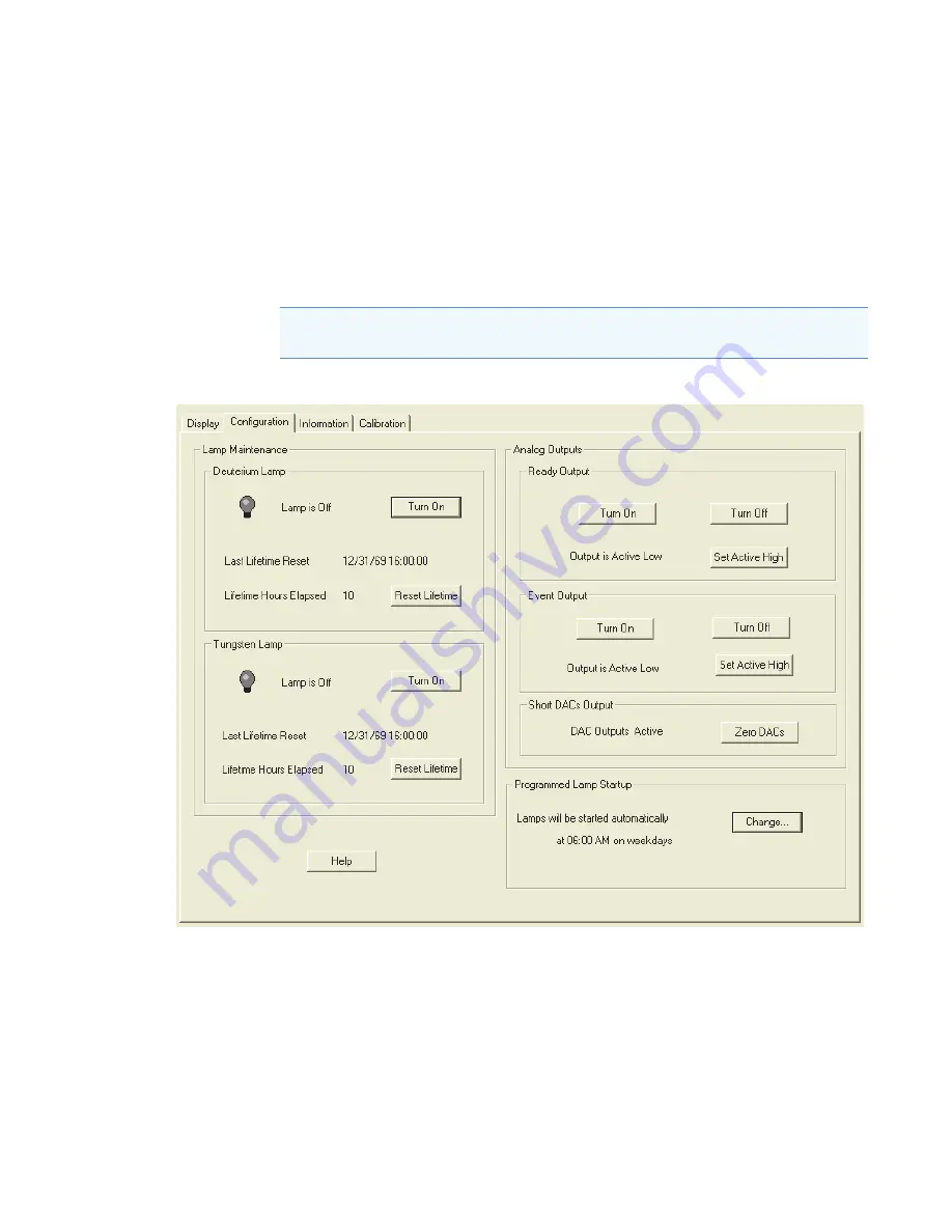
Figure 52. 

Surveyor PDA Plus Direct Control dialog box – Configuration page

Note  

Avoid indiscriminately pressing the Reset buttons. They should be pressed only 

after their associated lamp has been replaced with a new one.

Summary of Contents for Surveyor PDA Plus

Page 1: ...Thermo Surveyor PDA Plus Detector Hardware Manual 60053 97107 Revision F December 2013...

Page 2: ...e contents of this document are subject to change without notice All technical information in this document is for reference purposes only System configurations and specifications in this document sup...

Page 3: ...from Thermo Fisher Scientific or one of its authorized representatives Surveyor PDA Plus Detector EMC Directive 89 336 EEC EMC compliance has been evaluated by Underwriters Laboratories Inc Low Voltag...

Page 4: ...he instrument are not impaired Deviations from specified instructions on the proper use of the instrument include changes to the system and part replacement Accordingly order replacement parts from Th...

Page 5: ...Directives and the recyclers in your country WEEE Konformit t Dieses Produkt muss die EU Waste Electrical Electronic Equipment WEEE Richtlinie 2002 96 EC erf llen Das Produkt ist durch folgendes Symb...

Page 6: ...compagnies de recyclage dans chaque tat membre de l union europ enne et ce produit devrait tre collect ou recycl par celles ci Davantage d informations sur la conformit de Thermo Fisher Scientific ce...

Page 7: ...fahr durch entz ndbare Substanzen Beachten Sie die einschl gigen Vorsichtsma nahmen wenn Sie das System in Gegenwart von entz ndbaren Substanzen betreiben Peligro por sustancias inflamables Tenga much...

Page 8: ...away from this area Quetschgefahr Halten Sie Ihre H nde von diesem Bereich fern Puntos de pinzamiento Mantenga las manos apartadas de esta rea Risque de pincement loigner les mains de cette zone Heav...

Page 9: ...t surface Before touching allow any heated components to cool Flammable substances hazard Use care when operating the system in the presence of flammable substances Risk of eye injury Eye injury could...

Page 10: ...UV Sharp object Avoid physical contact with the object Pinch point Keep hands away from this area Heavy objects Never lift or move the instrument by yourself you can suffer personal injury or damage...

Page 11: ...Setting and Fuses 10 Making the Back Panel Connections 11 Connecting the Ethernet Cable 11 Connecting the Interconnect Cable 11 Connecting the Analog Outputs 13 Setting the Analog Output Voltage 14 S...

Page 12: ...etector 63 Calibrating the Detector with ChromQuest 63 Preparing the Detector for Calibration 64 Performing a Wavelength Calibration 65 Performing an Array Calibration 69 Displaying Printing and Clear...

Page 13: ...Log Entries 101 Critical Failure Messages 101 Warning Messages 101 Information Messages 102 Chapter 8 Accessories and Replaceable Parts 103 Appendix A Firmware 107 Installing the Update Files for Chro...

Page 14: ......

Page 15: ...Related Documentation In addition to this guide Thermo Fisher Scientific provides the following documents for the Surveyor MS Pump and the Surveyor MS Pump Plus Surveyor Plus Preinstallation Requireme...

Page 16: ...contains a LightPipe flow cell that you can easily damage if you handle it by its ends Do not to touch the fiber optics that are exposed at the ends of the flow cell See the following figure CAUTION H...

Page 17: ...nt do the following Keep good records Read the manufacturers Material Safety Data Sheets MSDSs for the chemicals being used in your laboratory Remove particulate matter from your samples before you in...

Page 18: ...ide a line of high purity or HPLC grade reagents that are free of chemical impurities Routine filtration of all solvents or eluents through a 0 45 or 0 2 micron or less fluorocarbon filter before plac...

Page 19: ...com en support landing support html To copy manuals from the Internet Go to mssupport thermo com agree to the Terms and Conditions and then click Customer Manuals in the left margin of the window To...

Page 20: ......

Page 21: ...rdware Manual 1 1 Introduction The Surveyor PDA Plus Detector is a member of the Surveyor Plus family of LC instruments see Figure 1 Figure 1 Surveyor PDA Plus Detector Contents Functional Description...

Page 22: ...0 nm There is some overlap between the two lamps in the 300 to 500 nm range Manually adjusting the two attenuators increases or decreases the light intensity reaching the photodiode array The optical...

Page 23: ...a 20 Hz rate the light intensity at each diode is converted into a 20 bit digital word and these words are stored in a dual port Random Access Memory RAM on the CPU PCB As the data points are stored...

Page 24: ...ll with end caps to protect these optical fibers see Figure 6 Do not remove the protective end caps until you install the LightPipe flow cell Replace the protective end caps for storage if you remove...

Page 25: ...mware is being downloaded to the CPU of the detector Green Communication to the data system PC has been established Run Amber The PDA detector is not ready to start a run for one of the following reas...

Page 26: ...Hz user selectable Rise Time 0 0 0 1 0 2 0 5 1 2 5 or 10 s user selectable Cell Dimensions 10 mm LightPipe flow cell 50 mm LightPipe flow cell Cell Pressure Rating 1000 psi Diodes 512 Diode Spacing 1...

Page 27: ...an be used as a quick reference of how to conduct a successful installation Make a copy of the checklist fill it out when the installation is complete and include it in your maintenance records Conten...

Page 28: ...age 9 Check the power settings and fuses see page 10 Make the initial back panel connections see page 11 Connect and install the LightPipe flow cell see page 15 Power on the detector for the first tim...

Page 29: ...e missing contact your Thermo Fisher Scientific representative immediately The part numbers of the accessory kit items are listed in Table 9 on page 105 Making the Initial Instrument Preparations Plac...

Page 30: ...holder pops out 2 Pull the fuse holder out of the power entry module 3 Verify that the fuse holder contains the appropriate size fuses T3 15 A for 100 115 V or T1 6 A for 230 V 4 If necessary slide ou...

Page 31: ...thernet Cable Connect the Ethernet switch to the Ethernet connector port of the PDA detector using the supplied CAT5 7 ft long shielded Ethernet cable with ferrite clamp Connecting the Interconnect Ca...

Page 32: ...acle on the back panel of the Surveyor LC Pump Plus 3 Plug the autosampler connector which is identified by the tag on its adjacent cable into the left 8 pin receptacle on the back panel of the autosa...

Page 33: ...quency interference and is most effective if the bare wire is grounded at just one end At the detector back panel there are three different analog voltage outputs per channel CHA 10 mV CHA 100 mV CHA...

Page 34: ...ge the unit ID setting for your detector unless you are controlling more than one PDA detector from one computer For details on configuring your detector see Chapter 3 Configuration Use a small flathe...

Page 35: ...nal device and connect the PDA EVENT output pin 8 to the negative input terminal of the external device Installing the LightPipe Flow Cell The LightPipe flow cell is packed in a small separate box wit...

Page 36: ...cess cover 3 Unscrew the retaining block knob and remove the retaining block see Figure 14 Figure 14 View of the retaining block and the retaining block knob STANDARD FILTER WHEEL 1 OPEN 2 HOLMIUM OXI...

Page 37: ...the flow cell outlet to an MS detector use the PEEK fittings to connect one end of the 0 005 in ID PEEK red tubing which is included in the MS detector accessory kit to the outlet port of the flow cel...

Page 38: ...tlet tubing connections for the 50 mm LightPipe flow cell 9 Replace the detector flow cell access cover making sure that the inlet and outlet tubing pass through the slots see Figure 13 on page 16 wit...

Page 39: ...Appendix A Firmware If the switches have been set to 00 turn the PDA detector off and use a small flat head screwdriver to reset the switches to an appropriate value 01 to 99 See Chapter 3 Configurati...

Page 40: ...icon to open the Instrument Setup view 5 In the viewbar click the Surveyor PDA button The Instrument Setup view for the PDA detector appears 6 On the menu bar choose Surveyor PDA Direct Control The PD...

Page 41: ...st To change the polarity of the remote outputs 1 Install the ChromQuest data system if you have not already done so 2 Add the Surveyor PDA Plus Detector to the instrument configuration see Configurin...

Page 42: ...gnment of components on the optical bench within the unit Bumps and jars which might occur in shipping and during the installation process can affect this alignment The detector is calibrated from the...

Page 43: ...m The only configurable option for the PDA detector is its stack address which must match its unit ID The unit ID is set by adjusting the two rotary switches on the back panel of the detector As Figur...

Page 44: ...our instrument in Xcalibur 1 Open the Instrument Configuration dialog box by doing one of the following For Xcalibur 2 0 x or lower from the computer desktop choose Start All Programs Xcalibur Instrum...

Page 45: ...lick a device in the Available Devices list it appears in the list of configured devices 3 Complete the configuration of the Surveyor PDA Plus Detector as follows a Double click the Surveyor PDA Pus b...

Page 46: ...f ChromQuest you are using do one of the following For ChromQuest SI choose Start All Programs Chromatography ChromQuest SI Config The ChromQuest SI Configuration dialog box appears Click Instrument C...

Page 47: ...st 5 0 or Surveyor previous versions of ChromQuest If you want to erase the configuration for a previously configured Surveyor Plus LC stack or change the instrument type to Surveyor select Thermo Sur...

Page 48: ...lus Configuration dialog box appears Figure 24 PDA Plus dialog box f In the Stack boxes type or select the appropriate stack address Unless you are controlling more than one Surveyor PDA Plus Detector...

Page 49: ...A Plus Detector Hardware Manual 29 10 If you have not already done so configure the remaining modules of your Surveyor Plus LC stack 11 Click OK to close the to the Thermo Surveyor LC or Surveyor dial...

Page 50: ......

Page 51: ...libration Performing a Dark Current Calibration Performing a Wavelength Calibration The alignment of the spectrum on the diode array is dependent upon the physical alignment of various components of t...

Page 52: ...Setup window appears b From the menu bar choose Surveyor PDA Plus Direct Control The Surveyor PDA Plus Direct Control dialog box appears c Click the Configuration tab The Configuration page appears d...

Page 53: ...Figure 27 do the following a Choose a peak set from the list The peak set should span the wavelengths you use under normal operation conditions In Figure 27 the Holmium Oxide 5 peak set is selected U...

Page 54: ...ibration wizard with a list of calibration files 5 On page three of the Wavelength Calibration wizard do the following a Observe the status screen that tells you the wavelength file is downloading see...

Page 55: ...ive 7 Click Next to proceed 8 On page five of the Wavelength Calibration wizard do the following a Observe the status screen see Figure 30 The diagnostics program waits for a few seconds for the rise...

Page 56: ...age six of the Wavelength Calibration wizard see Figure 31 The next button becomes active see Figure 32 Figure 31 Page six of the Wavelength Calibration wizard Figure 32 Page seven of the Wavelength C...

Page 57: ...ure and then repeat the wavelength calibration If after applying a second calibration the Delta values are still not within the range of 1 nm call your Thermo Fisher Scientific service representative...

Page 58: ...13 On page eight see Figure 33 click Apply The final page of the Wavelength Calibration wizard appears see Figure 36 14 Click Finish to complete the calibration The detector saves the calibration inf...

Page 59: ...henever a significant temperature change occurs After you move the detector After you replace the lamp After you download a new firmware file Because the dark current produced by the diodes rises as t...

Page 60: ...ea The Preconditions page appears see Figure 38 Figure 38 Preconditions page of the Dark Current Calibration wizard 5 Read the Preconditions page and verify that they have been met If the precondition...

Page 61: ...bserve the status readback as the calibration proceeds When the calibration is complete click Next Page three of the Dark Current Calibration wizard appears see Figure 40 You can export the results of...

Page 62: ...urveyor PDA Plus Detector Hardware Manual Thermo Scientific Once you have saved the file with a name of your choice you can view or print the contents of the file using any text editing program see Fi...

Page 63: ...k Current Calibration dialog box appears see Figure 43 Figure 43 Final page of the Dark Current Calibration wizard 9 Click Finish to complete the calibration The detector stores the calibration result...

Page 64: ...log collects messages regarding major events and errors occurring in the detector These messages are created as part of the normal operation of the detector and can be helpful when you are attempting...

Page 65: ...d monitor the status of the lamps you create a display method and then view a spectrum of the light intensity in the Surveyor PDA Plus Direct Control Spectrum page Display methods have an SPDA file ex...

Page 66: ...ee Figure 46 2 In the Surveyor PDA Plus Method page enter the appropriate parameters a In the Units area select the Diode Intensity option to set the X axis of the spectrum on the Display page to diod...

Page 67: ...detector is running as desired by performing the following operation verification procedure on your Surveyor PDA Plus Detector To verify the proper operation of the Surveyor PDA Plus Detector perform...

Page 68: ...r click the Surveyor PDA Plus button to open the Surveyor PDA Plus Instrument Setup view c From the menu bar choose Surveyor PDA Plus Direct Control to open the Direct Control dialog box 3 Make sure t...

Page 69: ...ating a display method Figure 48 Surveyor PDA Plus Method page with the selection of the Diodes Intensity option 2 Load the display method to the detector as follows a From the menu bar choose Surveyo...

Page 70: ...with future scans Date the printout and add it to your maintenance records Figure 49 Viewing a scan of the deuterium lamp intensity diodes 35 52 77 Viewing an Intensity Scan of Both Lamps To view an i...

Page 71: ...to open the Open Display Method dialog box Browse to the method that you created to monitor both lamps Then click Open to load the method The method filename appears in the box above the Spectrum plot...

Page 72: ...tor as follows a Choose Surveyor PDA Plus Direct Control to display the Surveyor PDA Plus Direct Control dialog box b Click the Display tab to open the Display page c In the Control area click Load Me...

Page 73: ...r the PDA Detector Verifying Operational Performance Thermo Scientific Surveyor PDA Plus Detector Hardware Manual 53 Figure 51 Display page with an intensity scan of the light output from the Tungsten...

Page 74: ...roximately 1000 hours and the tungsten lamp has a lifetime of approximately 2500 hours Lamp lifetime varies depending upon the application Perform the following procedures in the Configuration page of...

Page 75: ...e Click Reset Lifetime for the associated lamp The stored total run time for the associated lamp is reset to zero and the Last Lifetime Reset readback is updated to the current date and time Figure 52...

Page 76: ...igure 53 Lamp Startup Time dialog box 2 Click in the Xcalibur should start the lamps at box Then use the keyboard arrow keys the number keys or both to change the time 3 Click OK to apply the new lamp...

Page 77: ...intensities in the specified operating ranges To access the attenuators 1 Open the front doors of the detector 2 Loosen the captive screw and then remove the flow cell cover see Figure 13 on page 16...

Page 78: ...or MS Pump button to open the instrument setup view for the pump b Choose Surveyor LC Pump Direct Control or Surveyor MS Pump Direct Control The Direct Control dialog box for the pump appears c Select...

Page 79: ...the attenuators as follows a In the Control area click Start The spectrum of light intensities appears in the top window see Figure 55 For the UV region the diode of maximum intensity is between diode...

Page 80: ...bur Diagnostics for the PDA Detector Adjusting the Attenuators 60 Surveyor PDA Plus Detector Hardware Manual Thermo Scientific Figure 55 Display of intensity spectrum from diode number 2 to diode numb...

Page 81: ...Surveyor PDA Plus Direct Control dialog box To open the Information page in Xcalibur 1 On the menu bar of the Surveyor PDA Plus Instrument Setup view choose Surveyor PDA Plus Direct Control 2 Click t...

Page 82: ......

Page 83: ...Detector see Configuring the Surveyor PDA Plus Detector in ChromQuest on page 26 Calibrating the Detector with ChromQuest To calibrate the PDA detector from the ChromQuest data system prepare the det...

Page 84: ...r Then pump HPLC grade water or HPLC grade methanol through the flow cell for at least one hour 2 Turn on both lamps and wait one hour for the D2 lamp to equilibrate a In the menu bar of the online In...

Page 85: ...ector and uses the detector s wavelength algorithm to correct for any misalignment To perform a wavelength calibration with ChromQuest 1 On the Instrument Status page for the PDA detector click Diagno...

Page 86: ...igure 60 Diagnostics dialog box Calibration page with the Holmium12 Wavelength Calibration File selected Note ChromQuest has four calibration files to choose from The HolmiumUV file contains five wave...

Page 87: ...mobile phase When the background collection is complete the following dialog box appears see Figure 62 Figure 62 Message reminding you to move the filter wheel to position 2 6 Move the filter wheel t...

Page 88: ...a values are still not within the range of 1 nm call your Thermo Fisher Scientific service representative for assistance Figure 64 Diagnostics dialog box Calibration page with a list of acceptable Del...

Page 89: ...the lamps for 1 hour before you perform a dark current calibration Warming up the lamps for 1 hour allows the detector to equilibrate to its normal operating temperature ChromQuest briefly turns the l...

Page 90: ...and major detector events such as power on self tests POSTs are logged to a dedicated area in the memory of the detector The log can hold 100 errors events When the log is full the next entry replaces...

Page 91: ...strument Status page d Click Diagnostics to open the PDA Plus Diagnostics dialog box e Click the Error Log tab to display the Error Log page 2 Use the buttons in the Error log page to do the following...

Page 92: ...tus to display the Instrument Status window b Click the Surveyor PDA Plus tab to display the Surveyor PDA Plus Instrument Status page c Click Diagnostics to open the PDA Plus Diagnostics dialog box d...

Page 93: ...ure 68 j Save a printout or an electronic copy of the spectrum Date the printout and add it to your maintenance records To monitor any degradation in light intensity compare this scan with similar sca...

Page 94: ...tings to monitor diodes 94 177 and 260 c Click Load To Detector A dialog box containing the message Method Has Been Downloaded appears Click OK d Open the Display page and click Start to refresh the d...

Page 95: ...d To Detector A dialog box containing the following message Method Has Been Downloaded appears Click OK d Open the Display page and click Start to refresh the display e As with the D2 and combined lam...

Page 96: ...Performance 76 Surveyor PDA Plus Detector Hardware Manual Thermo Scientific 8 Turn on the deuterium lamp again and allow sufficient warm up time before you begin acquiring data Figure 70 Display page...

Page 97: ...romQuest print utility to print a copy of the Spectrum window To use the print utility 1 In the Display page place the cursor in the Spectrum window 2 Right click to open the shortcut menu 3 Choose Ut...

Page 98: ...hours Lamp lifetime varies depending upon the application In the ChromQuest data system the lamp controls are on the Lamps page of the PDA Diagnostics To open the Lamps page in ChromQuest 1 Open the...

Page 99: ...ored total run time for the associated lamp to zero and update the Last Reset readback to the current date and time After you replace a lamp reset its lamp usage hours to zero Adjusting the Light Outp...

Page 100: ...uest Main Menu double click the icon for your instrument to display the Instrument window c From the menu bar choose Control Instrument Status to display the Instrument Status window d In the Instrume...

Page 101: ...To Detector Determining the Diode of Maximum Intensity for the UV Range To determine the diode of maximum intensity for the UV Range 1 Click the Display tab to open the Display page 2 Click Start whi...

Page 102: ...he diode of maximum intensity for the visible range 1 Open the Axis Setup dialog box 2 Do the following a In the Min box type 400 b In the Max box type 500 c Click OK to close the dialog box and to up...

Page 103: ...s see Figure 73 The left tab is the deuterium lamp attenuator and the right tab is the tungsten lamp attenuator Pushing the attenuator tab up increases light output and pulling the tab down decreases...

Page 104: ...or the detector in the PDA Plus Diagnostics Display page To open the Display page 1 On the menu bar in the Main Menu window choose Control Instrument Status 2 Click the Surveyor PDA Plus tab to open t...

Page 105: ...dures on a regular basis If you have any questions on proper maintenance or would like to arrange for a preventive maintenance program contact your Thermo Fisher Scientific Service Representative The...

Page 106: ...e reduces the frequency with which you need to clean your flow cell Wavelength Calibration After lamp replacement or as needed Dark Current Calibration Calibrating the dark current increases the linea...

Page 107: ...ise signal spiking erratic or drifting baselines low light intensity or increased backpressure This section contains the following procedures Removing the LightPipe Flow Cell Cleaning the Flow Cell wi...

Page 108: ...ock knob that holds the LightPipe retaining block in place Then remove the retaining block see Figure 76 5 Being careful not to touch the optical fibers at the ends of the LightPipe flow cell pull the...

Page 109: ...and the cleaning solvent that is going to be used to clean the cell 3 Flush the flow cell with 40 to 50 mL of cleaning solvent for example isopropanol or methanol CAUTION Do not disassemble the LightP...

Page 110: ...hromatographic system and the nitric acid solution that is going to be used to clean the cell 4 Prepare a 20 v v solution of nitric acid in HPLC grade water 5 Pump the nitric acid solution through the...

Page 111: ...light output becomes too low and adjusting the attenuators does not help replace the lamps The lamps are pre aligned on small mounting blocks to facilitate replacement The deuterium D2 and tungsten W...

Page 112: ...rew driver remove the screw that secures the metal plate covering the LED cable connection to the inside of the left door Figure 77 View of the screw that secures the metal plate covering the LED cabl...

Page 113: ...ut of the housing until the metal lamp compartment cover is accessible from the right side of the instrument 8 Make sure that you have allowed sufficient time for the lamps to cool Then remove the lam...

Page 114: ...ounting flange to free the lamp see Figure 82 Figure 81 Lamp connections Note Do not try to remove the lamps from their mounting assemblies Remove and replace a lamp its mount cable and connector as a...

Page 115: ...t pins on the lamp power supply board The connector for the tungsten lamp has two leads see Figure 81 b Loosen and remove the single Phillips head screw that secures the lamp mounting block see Figure...

Page 116: ......

Page 117: ...r corrective action Contents Detector Related Problems Log Entries Table 3 Troubleshooting detector related problems Sheet 1 of 4 Symptom Cause Remedy 1 Spikes on baseline a Continuous gas bubbles in...

Page 118: ...upturing flow cell d Leaking flow cell d Replace the flow cell e Insufficient lamp warm up e Allow a 30 minute warm up for normal operation and a 1 hour warm up for maximum sensitivity f Lamp aging or...

Page 119: ...s Thermostatically control the column temperature 4 No peaks or peaks much smaller than expected a Incorrect wavelength setting a Check the wavelength setting Make sure the correct file is selected b...

Page 120: ...No action is required 10 LED2 Comm a Green communications normal a No action is required b Amber no communications with PC system b Check the Ethernet connections and module configuration in the soft...

Page 121: ...es Information Messages Critical Failure Messages Critical failure messages indicate that the PDA cannot perform its function properly If a chromatographic run is in progress when a Critical Error occ...

Page 122: ...urrent Failed to calibrate wavelength No Fault Information Messages Information messages include Deuterium lamp was turned on Deuterium lamp was turned off Tungsten lamp was turned on Tungsten lamp wa...

Page 123: ...the accessory kit Table 4 LightPipe flow cell assembly parts Part Number Description 803265 01 Flow cell assembly with inlet outlet tubing and fittings 1 cm LightPipe 803237 01 Flow cell assembly with...

Page 124: ...ID Blue 803237 Flow cell assembly with inlet outlet tubing and fittings 5 cm LightPipe 126078 Fuse T3 15 A 5 20 mm for 100 115 V operation 126079 Fuse T1 6 A 5 20 mm for 230 V operation Table 8 Repair...

Page 125: ...cessory kit Part Number Description A3538 010 Cable adapter RJ45 14 D89FM A3638 110 Cable 4 pin RJ45 6040 0103 Analog cable stainless steel detector 00004 02511 Connector plug 8 pin 3 81 mm pitch Mini...

Page 126: ......

Page 127: ...Firmware PDA Plus For ChromQuest the firmware files and the Surveyor Firmware Upgrade utility reside on the ChromQuest CD Because they are not automatically installed during the installation of the da...

Page 128: ...mware Upgrade Utility on your computer For the Xcalibur data system these files reside in the following folder drive Xcalibur system Surveyor Firmware PDA_Plus For the ChromQuest data system these fil...

Page 129: ...up for a firmware download you can download the firmware files To download the firmware file to the detector 1 Double click the icon for the Surveyor Firmware Upgrade Utility application program see F...

Page 130: ...Surveyor PDA Plus Detector The status display at the bottom of the Surveyor Firmware Upgrade Utility window indicates that a connection has been made see Figure 85 CAUTION Do not interrupt the firmwar...

Page 131: ...Utility showing a successful connection to the Surveyor PDA Plus Detector c Under File Names click Browse to the right of App1 and then select the APP1 file PDA_Plus_ bin The filename appears in the A...

Page 132: ...er you close the Surveyor Firmware Upgrade Utility the connection with the Surveyor PDA will be terminated automatically b Depress the On Off switch on the front of the Surveyor PDA Plus Detector to t...

Page 133: ...verifying the operational performance of the detector 72 wavelength calibration of detector 65 ChromQuest CD firmware files 107 upgrade utilities 107 cleaning procedures external surfaces 87 flow cel...

Page 134: ...ll assembly parts 103 location of 87 removing the 87 safety precautions when cleaning 90 functional description 2 fuses 10 G ground terminals connecting 13 I Information page in Xcalibur figure 45 ins...

Page 135: ...f 19 rise time 6 rotary switches figure 14 S safety standards iii scan rate 6 screws LightPipe 87 short term noise 6 signal polarities of external devices 15 Snapshot button 77 specifications 6 stack...

Page 136: ......

Reviews: