background image

FSP200

33

Tempo Communications Inc.

1390 Aspen Way • Vista, CA 92081 USA • 800-642-2155
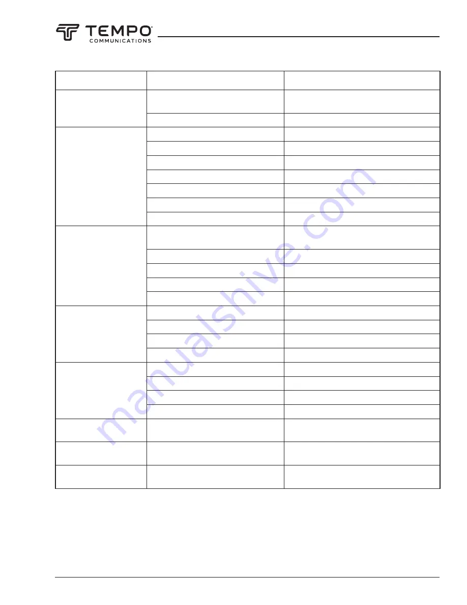
Error Message

Reason

Solution

Display “Wait Download..”

ON/OFF and ENTER buttons are held at the 

same time.

Power off. Power back on.

Component damage – keypad.

Keypad replacement required.

LEFT_FIBER_DIRTY

RIGHT_FIBER_DIRTY

LR_FIBER_DIRTY

Fibers are dirty.

Clean fiber and recleave.

V-grooves are dirty.

Clean V-grooves.

V-grooves are damaged.

V-grooves need to be factory replaced.

Fiber presser foot is dirty.

Clean presser foot of FSP200.

Fiber adapters are dirty.

Clean fiber adapters.

Mirrors are dirty.

Clean mirrors .

Lenses are dirty.

Clean lenses.

LR_ARC_VALUE_ERR

Fibers are dirty, passing the limit of 

checking process.

Clean fiber and recleave.

Cleave angle is too big.

Recleave fibers to obtain good cleave angle.

Failure to do the arc calibration.

Do arc calibration.

Electrodes are oxidized.

Clean electrodes or replace with a new pair.

Lenses are dirty.

Clean lenses.

FIBER_PUSH_ERR

Fiber is not in V-groove.

Replace fiber and check if fiber is in the V-groove.

Fiber holder is not tight.

Reposition the fiber.

Backward tension is on fiber.

Release any tension on fiber.

The adapter holder is dirty.

Clean the fiber adapter holder.

ARC_OFFSET_TOO_LARGE

Failure to do the arc calibration.

Do arc calibration.

Electrodes position error.

Check and or replace electrodes.

Electrodes are broken.

Replace electrodes.

Electrodes are oxidized.

Replace electrodes.

LENS_OFFSET_TOO_LARGE

Fiber is beyond observation range.

Perform “Screen Adjust” to allow fibers to be 

displayed on the screen.

COVER_OPEN when the 

windshell is closed

The magnet on windshell is missing.

Magnet needs to be factory replaced.

Notified to replace 

electrodes

Electrodes require calibration or 

replacement.

Stabilize electrodes as per Menu 3; replace 

electrodes.

Error Messages 

(cont’d)

Summary of Contents for FSP200

Page 1: ...NUAL Read and understand all of the instructions and safety information in this manual before operating or servicing this tool 52063481 REV 6 2019 Tempo Communications Inc 01 20 FSP200 Optical Fiber F...

Page 2: ...ing Procedure 14 Heating Protection Sleeve 15 Cooling Tray 16 Splice on Connectors 16 Button Functions 17 Appendixes 17 Section 3 Menu Operation 18 Splice Mode Menu S Mode 18 Heater Mode Menu H Mode 2...

Page 3: ...ice loss Contents List FSP200 fusion splicer 250 micron adapter pair 900 micron adapter pair SC LC splice on connector adapter SOC Oven adapter Spare electrodes one pair AC adapter power supply with N...

Page 4: ...ove Instrument Cover Do not remove the cover of the unit for any reason It contains no user serviceable parts SAFETY ALERT SYMBOL This symbol is used to call your attention to hazards or unsafe practi...

Page 5: ...e injury or death Electric shock hazard Use only AC adapter or battery charger designed for this splicer Using an improper AC power source could cause fuming electric shock or equipment damage Do not...

Page 6: ...ock or equipment damage This tool uses a three prong core AC power cord that contains an earthed ground safety mechanism This tool must be grounded Use only the supplied power cord Never use a two pro...

Page 7: ...battery It contains no user serviceable parts Failure to observe these precautions may result in injury and may damage the unit Do not store tool in areas of extremely high temperature and humidity D...

Page 8: ...discoloration damage or deterioration This tool requires no lubrication Oil or grease may degrade the splicing performance and damage the splicer This equipment must be repaired or adjusted by a qual...

Page 9: ...ut USB port Input Wind Protector LED Power Unit Dock Description of Products 2 Description and Function of Splicer Front Side of OFS 95 Back Side of OFS 95 Output USB port Input Wind Protector LED Pow...

Page 10: ...FSP200 Tempo Communications Inc 1390 Aspen Way Vista CA 92081 USA 800 642 2155 10 Top View Description of Products Top Side of OFS 95 Keypad of OFS 95...

Page 11: ...Turn off the splicer Push the release button located on the side of the splicer body and remove the battery Two Methods of Checking Remaining Battery Capacity If the battery is already installed in th...

Page 12: ...analyzing fiber profile and the splicing condition is chosen for the type of fiber The types of fibers covered by AUTO are all the conventional fibers such as SMF G652 BIF G657 NZDSF G655 MMF G651 et...

Page 13: ...upplied with the splice on connectors Clean optical fiber with alcohol soaked gauze or lint free tissue Dust particulates can enter the protection sleeve resulting in a fiber break or attenuation incr...

Page 14: ...or fiber chipping is detected the beeper sounds and an error message warns the operator The splicing procedure pauses If no error message is displayed the below stated end face conditions are used fo...

Page 15: ...n is first started or if the splicing environment has changed it is recommended that the technician perform an arc calibration 1 Place cleaved fibers into the splicer 2 Press and navigate to the Maint...

Page 16: ...inspect the finished sleeve to verify that no bubbles or debris dust is present in the sleeve Cooling Tray Place the splice into the cooling tray on the back of the FSP200 splicer Splice on Connector...

Page 17: ...Bright key for LCD Down key Dark key for LCD Start Stop heating protection Re calibrates arc power Resets the motor position Starts splicing work Switches between X Y and X Y views Appendixes Refer to...

Page 18: ...alibration works in this splice mode 2 AUTO SM For splicing standard single mode fiber ITU T G652 The MFD is 9 to 10 m at wavelength of 1310 nm Automatic arc calibration works in this splice mode 3 AU...

Page 19: ...MM1 For splicing multi mode fiber ITU T G651 Core diameter 50 0 to 62 5 m User can edit all parameters of this splice mode such as prefuse power prefuse time arc power arc time align proof test etc T...

Page 20: ...e splice mode Then press OK to confirm Note 1 AUTO SM NZ DS MM mode is recommended for splicing in most cases In this mode the splicer automatically adjusts splice parameters according to the fiber ty...

Page 21: ...mit in degrees Cleaning Arc Set or disable the duration of the cleaning arc Gap Increase the gap if the fibers are soft and melt too easily Decrease the gap if the fibers are hard to melt Gap Set Set...

Page 22: ...parameters The user will have to perform careful experiments with their individual fibers to obtain optimum results Heater Mode Menu H Mode There are 20 user programmable heating modes Select the one...

Page 23: ...In Select Heater Mode use the right arrow key to enter the Edit Heater Mode menu Edit Mode for Heater Settings Sleeve Type Enter the protection sleeve name Mode Title1 Enter the heater mode setting n...

Page 24: ...p into the hole of the electrode polisher and gently rotate the electrode 4 Wipe the electrodes with 99 pure IPA Do not touch the electrode surface with your fingers Now is a good time to clean the ob...

Page 25: ...he axial offset limit between the two fibers is violated Auto Fiber Forward Enabling allows the fusion splicer to advance the fibers towards each other upon closure of the windshield Realign after pau...

Page 26: ...mation at the splice This case often results in lower loss than case c Data Save The FSP200 stores up to 5000 splicing results Splice Memory The Splice Memory function allows the user to display expor...

Page 27: ...ck operation LCD Auto Turn Over Enable or disable the splicer for the LCD to display the splice screens when the LCD screen is tilted to a different axis Auto Heat Switch When enabled the heater will...

Page 28: ...When the password function is enabled select Set Password Select characters add spaces delete characters or confirm The password max length is 8 and it can be uppercase letters lowercase letters numb...

Page 29: ...Modes Adjustable 0 240 seconds Tube Heating Time Typical 18s 4 Attenuator Mode 0 1 to 15 dB Electrode Life 5000 Splices Display 3 5 Color Turn Over LCD Connectivity USB Operating Conditions Pressure...

Page 30: ...ty Check if fiber cleaver is clean and in good condition Prefuse power too low or prefuse time too short Increase Prefuse Power and or Prefuse Time MFD mismatch Arc power too low Increase Arc Power an...

Page 31: ...or Overlap Note A vertical line sometimes appears at the spice point when MM fibers or dissimilar fibers different diameters are spliced This does not affect splice quality such as splice loss or ten...

Page 32: ...e MM fiber Set Focus to Edge to splice indistinct core fibers i e MM fiber To splice distinct core fibers enter Auto or the correct focus value Left Right fiber X Y set error The fiber is not set cor...

Page 33: ...e arc calibration Do arc calibration Electrodes are oxidized Clean electrodes or replace with a new pair Lenses are dirty Clean lenses FIBER_PUSH_ERR Fiber is not in V groove Replace fiber and check i...

Page 34: ...poor fiber movement during fiber adjusting Clean them periodically Dust or dirt is on the lens or mirror If dust or dirt exists clean the lenses or mirrors Bad electrode condition Replace the electro...

Page 35: ...om the V groove with a clean dry lint free cotton swab V grooves Cleaved Fiber Figure 1 Figure 2 If the contaminants in the V groove cannot be removed with an alcohol impregnated lint free cotton swab...

Page 36: ...lean and free of streaks or smudges Turn on the power and make sure no smudges or streaks are visible on the monitor screen Press X Y to change the screen and check the state of the lens surface on bo...

Page 37: ...daily Refer to Figure 4 If the circular blade or clamp pads of the fiber cleaver become contaminated the cleaving quality could degrade This may lead to fiber surface or end face contamination result...

Page 38: ...iber type has a pre programmed splicing profile in the FSP200 Use this profile for splicing 4 If there is not an exact matching splice profile use the AUTO mode splicing profile 5 Splice a fiber pigta...

Page 39: ...icer Make sure to butt the 900 m buffer up to the edge of the fiber adapter This will ensure that the mini splice sleeve will adhere to both sides of the 900 m buffer Installation 1 Remove the factory...

Page 40: ...urer s instructions 6 Once the fusion splicing cycle is completed remove the connector from the splicer and slide the splice protection sleeve up to cover the splice Make sure that the splice protecto...

Page 41: ...ear excepting normal wear and abuse For all Test instrument repairs you must first request a Return Authorization Number by contacting our Customer Service department at toll free in the US and Canada...

Reviews: